Fire høje åbne beholdere til væsketryk
Created today
Description
Fire åbne beholdere i forskellige former, 250 mm høje, til et fysikforsøg hvor trykket i væskesøjlen måles i forskellige dybder. Formålet er at vise, at trykket afhænger af dybden og ikke af beholderens form. Hver beholder printes stående uden support, og trykmålerens slange sænkes ned fra toppen.
Mål
- Cylinder: Ø50 mm
- Firkantet prisme: 46 × 46 mm
- Kegle med bred top: Ø40 mm i bunden, Ø80 mm i toppen
- Kegle med smal top: Ø80 mm i bunden, Ø15 mm i toppen
- Højde 250 mm, væg 2,4 mm, bund 3 mm
Remix-muligheder
- Højde (250 mm): Bambu Lab P1S og P2S har 256 mm i Z, så 250 er næsten loftet. Sænk den for mindre vandvægt og mere stabilitet.
- Væg (2,4 mm): Øg til ca. 3 mm for flere perimetre i PETG, hvis væggene skal være ekstra tætte.
- Topdiameter på keglerne: Ændr forholdet mellem top og bund for stejlere eller fladere sider. Hold hældningen under ca. 45° for print uden support.
- Variant: Tilføj en målestuds i siden til slange eller føler, eller en bredere fod til de smalle beholdere, så de står stabilt.
- Passer sammen med: en trykmåler med slange, en målestok langs siden og farvet vand for aflæsning.
Images
More like this
Explore more in Workshop & Tools →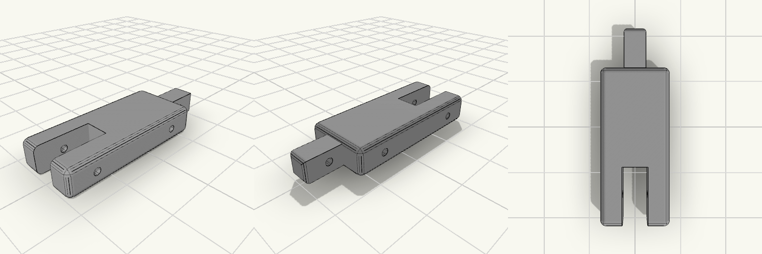
Bracelet Link Fit Gauge Block
A bracelet repair print that turns out too tight or too loose wastes hours. This fit gauge block is a 15-minute test piece that checks the fork slot and pin bores before the real part gets printed. Key numbers Block: 14 x 32 x 6 mm, origin at center, 1.2 mm edge fillets Fork slot: 5.2 mm wide, 12 mm deep, open at the -Y end, flat end wall at Y = -4 Prongs: 4.4 mm wide each Bores: Ø1.6 along X at Y = -10 (through both prongs) and Y = +10 (solid section) Tongue sample: 4.4 x 4.6 mm, 8 mm long on the +Y end, 0.9 mm end fillets, Ø1.6 bore at Y = +19 (40 mm overall) Printing Flat on the bed, PLA or PETG, 0.4 mm nozzle, 0.2 mm layers 4+ walls, 100% infill, 3 mm brim, no supports, 40 mm/s or slower Ream both bores once by hand with a 1.5 mm drill bit Checks A bracelet tongue link should enter the slot with slight friction. An original pin should slide through the -Y bore.
Funnelpour — Screw Sorting Tray
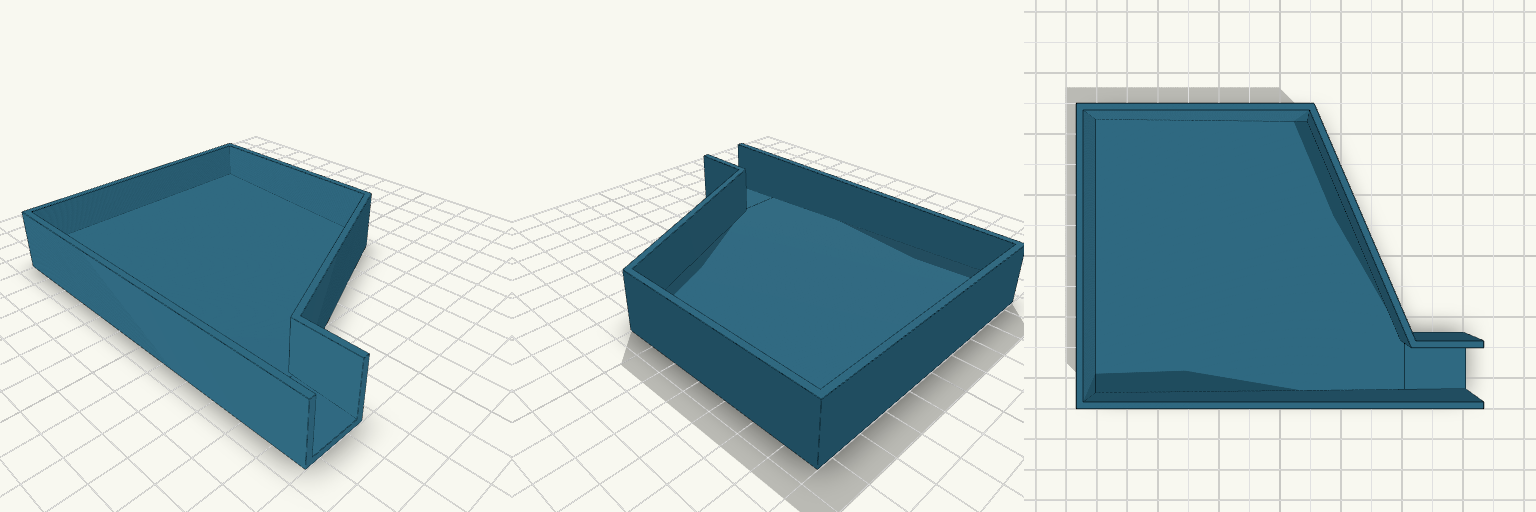
Funnelpour is a shallow sorting tray built for one job: tip a handful of loose screws in, pick out what you need, then pour the rest back into the jar without scattering them across the bench. The floor slopes toward a single open spout in one corner, and the walls taper inward to funnel everything into a 20 mm pour opening. Features Sloped floor: about 8 mm thick at the far end, falling to 2 mm at the spout, so screws roll toward the pour edge. Funnelled walls: the back-right wall angles inward from the main body down to the spout. Open spout: a 20 mm wide opening with no lip, sized to feed a jar mouth. Wall height: 20 mm walls with 2 mm wall thickness keep screws contained while sorting. Dimensions Overall footprint: 120 × 90 mm Height: 20 mm Spout width: 20 mm Print notes Prints flat on the base with no supports needed. The slope runs along the length rather than diagonally, so a slight tilt of the tray helps clear the far back corner when pouring.
Flat Ground Plate 45x42x2 mm with Tabs
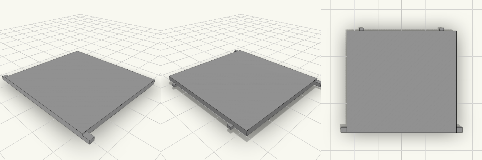
Flat 45 × 42 × 2 mm ground plate with two side tabs on the front 45 mm edge and two small blocks on the back edge. Overall width across the tabs is 50.4 mm. Plate: 45 × 42 × 2 mm, sharp edges Side tabs: 1.4 mm thick, flush with the underside, 50.4 mm overall span Back blocks: 1.5 mm wide, 1 mm thick, 1.5 mm protrusion, 5 mm from each side edge Print flat, no supports needed
サーボソケット
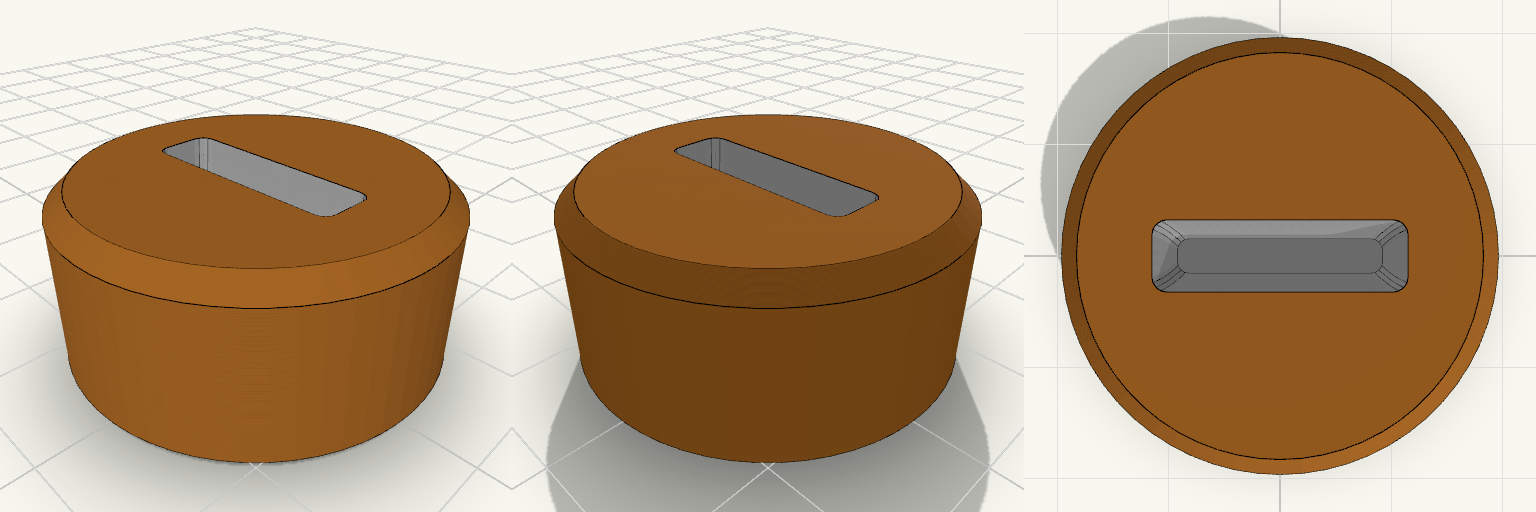
A servo can't turn a valve knob without a socket that grips it, and a loose fit slips under torque. This cylindrical socket slides onto the knob from the bottom and keeps the top face flat and closed for a future servo horn. Key numbers Body: 30 mm diameter, 14 mm tall, chamfered edges Cavity depth: 10 mm, opening only on the bottom face Opening at the bottom: 2.6 mm × 16.7 mm, widening to 4.5 mm × 16.7 mm at the inner end Clearance: 0.15 mm per side, with rounded corners and slightly bowed long walls Top wall: 4 mm solid, with no screw or mounting holes Printing: open face down on the bed, no supports needed; the wall slope is about 5° from vertical Cavity size, taper, corner radius and clearance are all adjustable parameters
Drill Press Column Tray with Key Slot
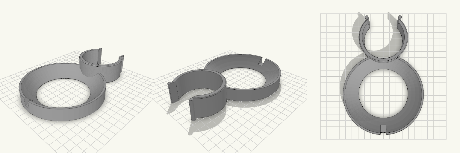
A C-shaped clip that snaps around a 60 mm drill press column, with a 120 mm round dished tray attached at the front. The tray holds drill bits, chuck keys and small parts within reach while you work. The clip opening is narrower than the column, so it snaps on and grips by spring tension. Lead-in lips on both sides of the opening guide it onto the column. A slot on the front rim of the tray holds the chuck key, so it stays off the floor. Clip: fits a 60 mm column, 30 mm tall, 5 mm wall Tray: 120 mm diameter, 18 mm tall, with a 3 mm floor and a dished cavity Key slot: on the front rim, 9 mm wide, sized for a chuck key shaft Print the clip upright with the tray on the plate. PETG or ABS gives the clip better flex and durability than PLA.
Tape Spindle and Zip Tie Bench Caddy
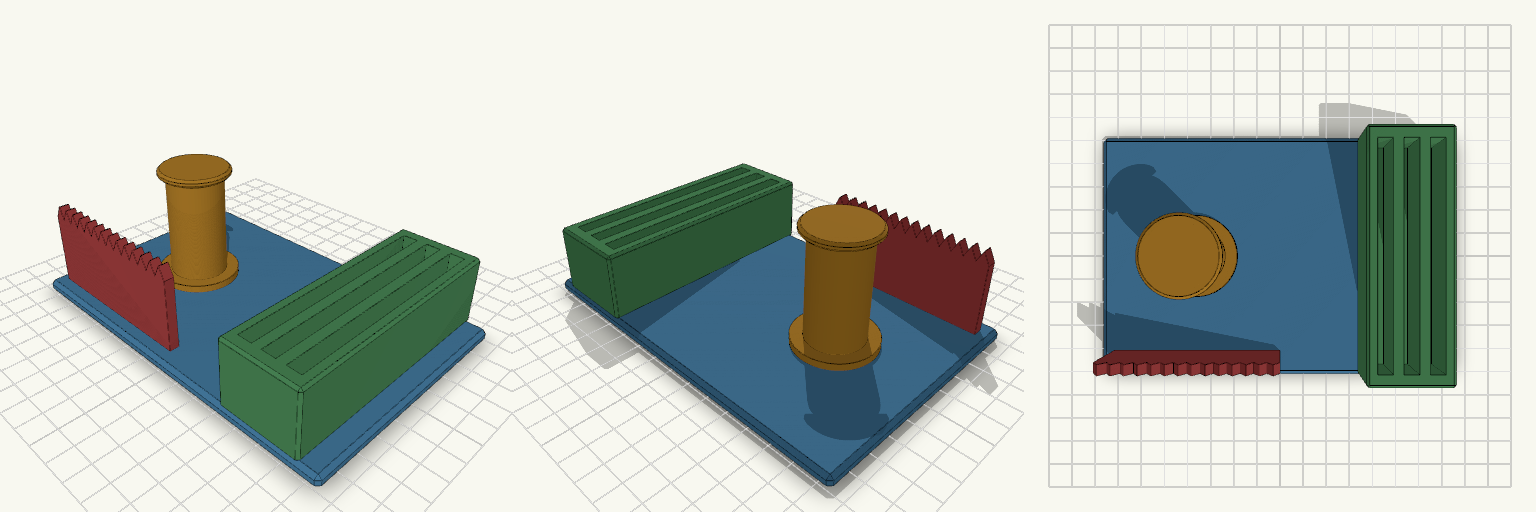
Bench caddy that keeps a tape roll and a bundle of zip ties in one fixed spot on the bench. A 24 mm spindle holds a roll with a 25 mm core. A serrated tear bar runs along the front edge so tape can be pulled across the teeth and torn. A block on the right has three slots for zip ties up to 90 mm long. Specs Base: 150 × 100 × 5 mm plate with 1.5 mm chamfered edges Spindle: 24 mm diameter, about 46 mm tall, with a 34 mm foot and a 30 mm top flange. Sized for a 25 mm core with 1 mm clearance. Tear bar: 70 mm long, 4 mm thick wall with 14 serrated teeth. It sits along the front (-Y) edge, beside the spindle. Tie trough: 34 × 100 mm block, 28 mm tall, with three 6 mm wide slots, each 90 mm long, in a row across X. Overall height: about 54 mm, measured at the top of the spindle flange. Material: PLA or PETG. Print flat on the base with no supports. Notes Fit has not been tested against a physical roll. If the roll is tight on the spindle, reduce the spindle diameter slightly. Slot width suits standard narrow zip ties. Wider ties need wider slots.