Guillotine Wire Cutter with NEMA 17 Screw Drive
Created today
Remixed 3 times
Description
A wire cutter that pinches the wire and spits it back instead of shearing it is the failure this guillotine is built around. Two 8 mm screws, one down each side, move a split carriage whose two V blades pass each other with no face gap, so the cut closes from the sides toward the middle instead of trapping the wire. The base and the bottom blade holder print as one piece, so nothing loosens or pries up under the cutting load, and each flanged nut is captive inside the split carriage, so nothing sticks up into the switch area and the carriage is pulled down as well as lifted.
Fit and print numbers
- Cutting height: the bottom blade's V bottom sits exactly 53 mm above the base underside, set to line up with a feeder. The holder stands 42 mm tall and grips 18 mm of the blade; the blade bolt head is open at the front, so a blade change needs no channel cut into the base.
- Base and blade holder: one piece, 132 × 45 × 42 mm overall, with a 6 mm base that sits just around the motors.
- Split carriage: lower half 128 × 28 × 16 mm, upper half 128 × 28 × 8 mm. Four M3 × 10 mm bolts clamp the halves, with the nuts trapped in the lower half. Each flange sits in a 22.8 mm round pocket, 3.5 mm deep, at the joint, and the 2 mm stub rises into a relief in the upper half. No bolts go through the flange holes.
- Drive: two NEMA 17 motors, 41 × 41 × 37 mm, bolted down with four M3 screws on the standard 31 mm pattern — 3.4 mm clear holes with 6.2 mm counterbores underneath. The two 8 mm screws are 100 mm long, joined to the motor shafts by 25 mm couplers (12.5 mm on the 5 mm shaft, 12.5 mm on the screw).
- Top plate: 130 × 42 × 10 mm in one piece, with no bearing in it. Each screw passes through a plain 8.6 mm hole, and the plate is sandwiched between two 8 mm clamping shaft collars (about 16 mm OD, with set screws) — one under the plate, one on top. A flat M8 washer on each side cuts friction. The collars clamp anywhere on the screw, so the screw ends can be trimmed; they currently stand about 15 mm above the plate. T8 nuts above and below the plate are the alternative if you would rather not use collars.
- Blades: each V blade is 10 × 2.5 × 34 mm, standing upright, with a 5 mm deep V notch — 29 mm to the V bottom at the centre — and a 3.3 mm hole centred 3 mm from the held end. The top blade sits 2.5 mm behind the bottom one, one blade thickness, so the faces touch. At the open position the blade tips are 8 mm apart and the V bottoms are 18 mm apart vertically. A 6 mm wire clears only if it sits centred side to side. An M3 bolt enters from the front through the hole into a hex nut trap in the back face of the holder, so a blade can be changed without splitting the carriage.
- Limit switch: 20 × 6 × 10 mm body with a roller underneath. The body sits in a 20.4 × 6.4 mm slot in the top plate, wires running out the top. The slot sits at X = -22, clear of the screw hole and the collars. The roller hangs below the plate directly over the flat top of the carriage, and the carriage itself trips it after about 8.5 mm of upward travel — no trigger post to print or lose.
Tolerances already in the model
- Blade pockets: 10.6 × 3.1 mm for the 10 × 2.5 mm blade, about 0.3 mm of play per side.
- Blade bolt holes: 3.6 mm for M3.
- Flange pockets: 22.8 mm for the 22 mm flange.
- Barrel holes: 11 mm for the 10.2 mm barrel.
- Screw holes: 8.6 mm for the 8 mm screw.
Fitting the flanged nuts
The carriage splits at the flange, so the nut drops in rather than being pushed through anything.
- Lay the lower half with its joint face up.
- Drop the nut in barrel first — the barrel goes down through the 11 mm hole until the flange sits in its pocket.
- The 2 mm stub points up out of the pocket.
- Set the upper half on top; its relief takes the stub and the flange is clamped between the halves.
- Fit the four M3 bolts.
Print layout
The model comes as four parts, each flat on the bed with no supports, in a footprint of about 132 × 167 mm:
- Base and blade holder in one piece, standing upright.
- Top plate, flat on its bottom face.
- Carriage lower half, flipped so its joint face is on the bed and the blade pocket opens upward.
- Carriage upper half, joint face down.
At 0.2 mm layers and 15% infill the set is roughly 11 hours and 85–90 g: about 3.5 h for the base and holder, 3 h for the top plate, 3 h for the carriage lower half and 1.5 h for the upper half. Four perimeters, 10–15% gyroid infill and 4–5 top and bottom layers keep the strength where it matters — the perimeters carry the load in these parts, so slicer settings save more plastic than extra cut-outs would.
Split carriage and captive nuts
The split lets the flanged nuts sit inside the carriage instead of on top of it, so nothing sticks up into the switch area and the carriage can be pulled down as well as lifted. The bolts only clamp the halves; the flange presses on the printed halves in compression, not on the bolts.
- Print each half with its split face on the bed — both faces are flat, so no supports are needed.
- The lower half's blade pocket opens upward, so it prints cleanly.
- Layer lines run parallel to the joint; use extra perimeters around the bolt holes.
- The split also lets you change a nut without reprinting the whole carriage.
Before running it
- Set the lower end stop in your motor control. The V bottoms cross once the carriage bottom drops below about 70 mm, and the couplers stop it at about 58 mm, so there is roughly 12 mm of overlap. That is the only margin — do not rely on the hardware to end the stroke.
- Wire both motors to the same driver output, or to two drivers sharing step and direction. With no guide rods and no rear column, screws that drift out of step will twist the carriage and make it bind.
- The blades are modelled touching exactly. Two real faces with zero gap will rub, and printed pockets carry tolerance. If they bind, leave about 0.1 mm of clearance or a slight spring preload.
- Confirm the nut fit. The model uses a 15.5 mm overall nut: 10 mm threaded body, 3.5 mm flange and a 2 mm stub above the flange. If your 2 mm offset is meant to sit inside a 15 mm overall length, resize the pockets.
- Check the switch trips before the carriage reaches the top plate, and move the switch to the other side of the plate if your wire runs through on the left.
- Add side stiffness if the cut loads the frame. The top plate is held only by the screws and collars; two thin printed side rails from the base to the plate will resist flex better than extra plastic in the plate.
- Print the carriage and blade holder with layers running along their length, and use extra perimeters around the bolt holes and blade pocket.
Images
More like this
Explore more in Workshop & Tools →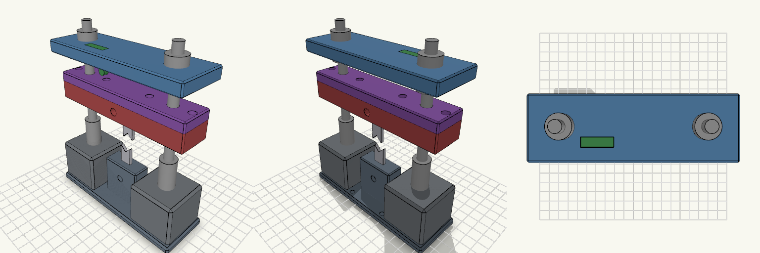
Twin-Screw Guillotine Wire Cutter
A guillotine wire cutter in the spirit of a workshop shear: two V blades pass each other with no face gap, driven by twin 8 mm lead screws on NEMA 17 motors. Design notes Base and bottom blade holder print as one upright piece. Split carriage captures the flanged nuts between two halves. Hex nut traps are 7.0 mm; blade holes sit 4 mm from the held end. Assembled view shows black motors, screws, nuts, blades and limit switch for visualisation only.
Spring-Loaded Pinch Roller Arm for Wire Feed
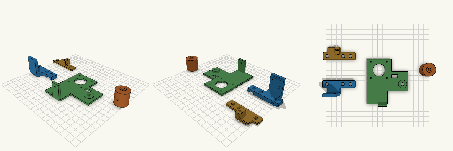
A wire feeder fails at the pinch point first: the wire skates sideways or gets crushed under a fixed idler. A spring-loaded pinch roller gives the idler somewhere to move. The pivoting arm carries an M6 bolt for your bearing idler and presses it onto the wire over the drive roller; the pivot and spring sit on +X so the -X side stays clear for the wire guide tube. The printable set is four parts — motor frame, pinch arm, arm cheek and drive roller — with the hardware left out of the print. What prints Motor frame: a trimmed plate, 16.5 mm shorter on the wire-tube end, with square-cut corners so it sits flush. The plate is cut back above the pivot boss and below the IR slot. It carries the 31 mm NEMA 17 hole pattern and 24 mm boss hole, the pivot boss with its M6 nut pocket, the spring bracket, and a 12 mm × 6.5 mm rectangular IR sensor slot on the pivot side. Pinch arm: the main half — pivot end, cheek, posts and raised cross-bridge with an M3 nut trapped in it for spring preload. The cheek is 14 mm tall, the pivot end has about 5.9 mm of plastic beyond the pivot hole, and the idler end stops 8 mm past the idler hole. Each cheek has one rounded 7 × 6 mm lightening window between the pivot recess and the posts, with at least a 4 mm rim around the holes. Its underside carries the groove the other half slots into. Arm cheek: the second half of the arm, held on by one M3 screw through the bridge into a trapped nut in a block on its inner face. It matches the pinch arm’s 14 mm cheek height and lengthened pivot end, and carries the same lightening window. The idler bolt passes through both halves into a trapped M6 nut, with about a 2 mm wall behind the widened pocket. Drive roller: 24 mm diameter, on a 5 mm D-bore through a 10 mm hub. The M3 grub screw has a trapped hex nut that slides in through a slot open to the rim. Print orientation Motor frame: lay it on its motor-side face directly on the bed. The M6 boss and spring bracket point up, and the nut pocket is on the bed face. The 12 mm slot is a vertical cut-through, so the frame prints without supports. Pinch arm: it lies flush on its bed face — the cheek and post are 7 mm thick so the nut boss no longer holds anything in the air. The pivot recess opens onto the bed face as a shallow pocket, not a bridged span. The 17 mm recess is wider than the 14 mm cheek, so it opens through the top and bottom edges; the full-thickness cheek behind it carries the load. The bridge wall is tall, so use 4–5 walls and slow the upper layers. No supports. Arm cheek: lies on its outer face, flat, with no supports. Drive roller: stand it on its end so it comes out round. The nut slot opens to the rim, so it prints without bridging. None of the four parts needs supports. Use 4–5 walls on both arm halves, since the joint is where the load passes; 3 walls and 25–30% infill on the roller, and the plate can go to about 20%. All four can be printed in the same black filament; the viewer colours only separate the parts. Rough total is about 80–115 g in PETG at 3–4 walls, but your slicer’s estimate will be better. The arm joint Tongue: a 2.5 mm wide, 1.8 mm tall rib, 18.9 mm long, on top of the arm cheek’s post. Groove: a 2.9 mm wide, 2 mm deep, 19.5 mm long slot in the underside of the bridge. It is closed at both ends, so the tongue stops the halves sliding sideways or lengthways. Fit: 0.2 mm clearance on each side of the tongue and 0.3 mm at each end, and the tongue stops 0.2 mm short of the groove roof so the post top sits flat against the bridge. Screw: one M3 × 14 down through the bridge into the trapped nut in the cheek block. The block sits outside the bearing’s swing, so the 30 mm roller clears it. The idler and pivot bolts clamp the halves as well. Test-fit the tongue and the nut slot before assembling the full arm. IR sensor slot The motor frame has a 12 mm wide by 6.5 mm tall rectangular slot through the plate on the pivot side, centred on the wire line — the nip between the rollers, about 12 mm above the drive roller’s axis — so a reflective IR proximity module looks across the wire. There is no shelf: the plate is a clean vertical cut-through and the frame sits flat on the bed for printing. The module board has to be held square with a dab of glue or a zip tie. The 6.5 mm height gives a 5 mm LED about 0.75 mm of clearance above and below. The slot is well out from the motor boss hole, so the two don’t meet. Check your module’s board thickness and LED height against the slot before printing. What it fits Idler: the arm carries an M6 × 35 bolt for a 30 mm × 25 mm bearing roller — head and washer on one side, trapped M6 nut in the cheek boss on the other, so the nut cannot spin while you tighten. The cheek gap is 26 mm against a 25 mm roller, so add a thin spacer each side so only the inner race is loaded. Spring: 14 mm long, 7 mm OD, 5 mm ID, between the raised cross-bridge and the frame bracket. The M3 × 22 screw threads into an M3 nut trapped in the 5 mm thick bridge, and turning it sets the preload. Pivot: 6.2 mm hole through the plate and boss, with a 5 mm deep hex pocket for an M6 nut on the back, so the arm is clamped by bolt and nut rather than by the printed boss alone. The arm cheeks were lengthened at the pivot end and made 14 mm tall to leave more material around the pivot hole; the idler end is now shortened and lightened. Clearance: the plate and pivot boss sit back so the arm cheeks clear the plate by about 4 mm and the drive roller hub by about 5.5 mm. That puts the roller further from the motor face — check the motor shaft actually reaches it before bolting anything down. Hardware to have on the bench | Item | Size | |---|---| | Idler bolt | M6 × 35 hex head, with M6 nut and washer | | Roller spacers | thin M6 washers or shims, about 0.5 mm each side | | Pivot bolt | M6 × 45, nut in the back pocket, nyloc nut and washers at the arm end | | Spring screw | M3 × 22 with M3 nut trapped in the bridge | | Arm joint screw | M3 × 14 with M3 nut trapped in the cheek block | | Drive roller grub screw | M3 × 6–8 set screw with M3 nut in the rim slot | | Spring | 7 mm OD, 5 mm ID, 14 mm long compression spring | | Frame screws | 4 × M3 × 8–10 on the 31 mm NEMA 17 pattern | Fit, force and checks before printing Pinch force: the spring sits close to the idler shaft, giving a ratio of spring distance to idler distance from the pivot of about 0.87 — nearly all the spring force reaches the wire. More pinch means a stiffer spring, not a longer screw. Roller gap: the 24 mm drive roller and 30 mm idler are set so their surfaces touch at the nip. There is no gap for the wire until the arm lifts. There is no stop screw, so the arm can close fully with nothing in it; set the preload with a piece of wire in place, or add a stop. Nut pockets: the M6 pockets are 12.2 mm across corners and the M3 pockets are 6.9 mm, with 6.2 mm side slots for the sliding nuts. Your under-5 mm nuts sit fully in the 5 mm deep M6 pockets. Still test-fit a nut before printing the full set. Filament: PETG for the frame and both arm halves, since the NEMA 17 plate runs warm and PLA creeps near it. PETG, ASA or nylon for the drive roller — nylon wears best, and a thin rubber or TPU sleeve adds grip if the wire slips. Before printing: the nut pockets, the tongue-and-groove clearance and the hole clearances are untested on your printer, so print the roller first and test-fit the nut before committing the rest. Keep the four parts in the orientations above, leave the hardware out of the print, and don’t overtighten the joint screw — that is the likelier way to crack the arm.
Funnelpour — Screw Sorting Tray
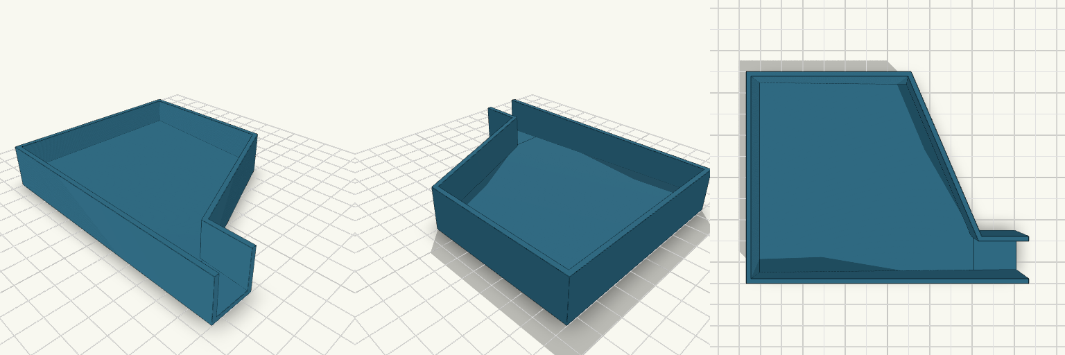
Funnelpour is a shallow sorting tray built for one job: tip a handful of loose screws in, pick out what you need, then pour the rest back into the jar without scattering them across the bench. The floor slopes toward a single open spout in one corner, and the walls taper inward to funnel everything into a 20 mm pour opening. Features Sloped floor: about 8 mm thick at the far end, falling to 2 mm at the spout, so screws roll toward the pour edge. Funnelled walls: the back-right wall angles inward from the main body down to the spout. Open spout: a 20 mm wide opening with no lip, sized to feed a jar mouth. Wall height: 20 mm walls with 2 mm wall thickness keep screws contained while sorting. Dimensions Overall footprint: 120 × 90 mm Height: 20 mm Spout width: 20 mm Print notes Prints flat on the base with no supports needed. The slope runs along the length rather than diagonally, so a slight tilt of the tray helps clear the far back corner when pouring.
5 x 5 x 1 mm Square Block
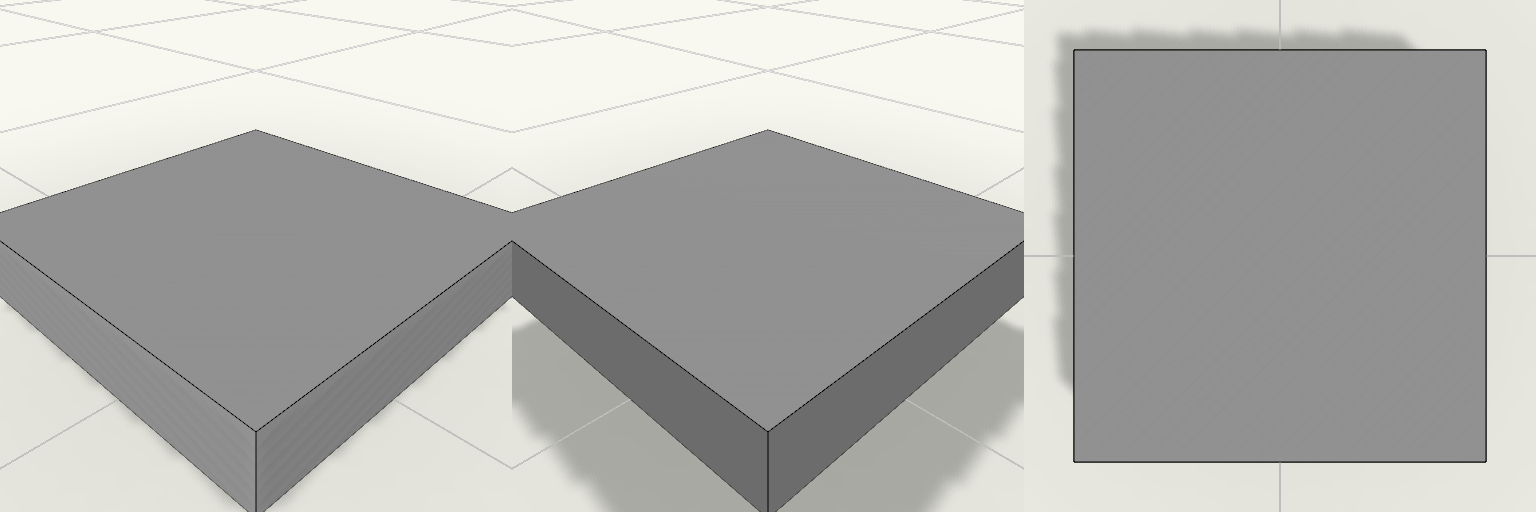
A plain square block measuring 5 mm by 5 mm by 1 mm, flat on the bed and ready to print. Remix hooks Footprint: 5 x 5 mm is the starting value. Change it to make a tile, spacer or shim. Thickness: 1 mm is about five layers at 0.2 mm. Raise it for a sturdier piece. Edges: Add a small chamfer or rounding for a softer look. Keep it under 0.5 mm at this size. Pairs with: Use it as a test cube for tolerance checks, or as a base for a hole, text or a peg.
Tape Measure Holster with Label Window
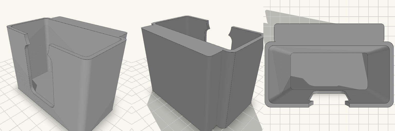
A belt-worn holster cup for a 5 m tape measure, sized for a body of about 75 × 75 × 35 mm with 2 mm of total clearance. A vertical window in the front lets you read the size label without pulling the tape out, and a round thumb scoop at the top edge makes it easier to grip and lift. A loop on the back takes a belt. The cup is open at the top and covers the lower 80% of the tape (60 mm). Outer size is 82 × 42 mm, with 2.5 mm walls and a 2.5 mm floor. Remix hooks Tape size: the tape width, height and thickness (75 / 75 / 35 mm) and the 2 mm clearance are the main numbers. Change them and the cup, loop and window all follow. Other tape brands or 3 m / 8 m sizes are a quick swap. Cup height: set at 80% of tape height (60 mm). Lower it for easier draw, raise it for a more secure hold. Label window: 30 mm wide, with rounded ends, centred on the front. Widen it for a bigger label, or move it to the side for a tape with an offset label. Thumb scoop: 26 mm diameter cut at the top front. Shrink it for a snugger hold. Belt loop: the slot is about 5 mm deep and the loop spans the back at 70 mm wide. Thicker or wider belts need a deeper slot, which is the first thing worth testing against your own belt. Wall thickness: 2.5 mm. Go thicker for rigidity, or thinner to save material. Pairs well with A flexible filament such as TPU for a grippier cup, or PETG for a stiffer loop. A second window on the back or side if you want to read the metric scale as well. A small retention tab or friction bump inside the cup rim if the tape needs a firmer hold.
Small Block 15x4x4 mm
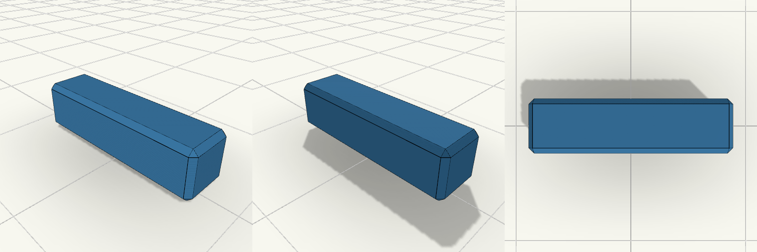
What it's for A small solid block for use as a spacer, shim, test piece or placeholder. Dimensions Length: 15 mm (X) Width: 4 mm (Y) Height: 4 mm (Z) Edges chamfered 0.4 mm Remix ideas Add a through hole for a screw or string. Increase the chamfer for a softer look. Engrave a label on the front face.