Spring-Loaded Pinch Roller Arm for Wire Feed
Created today
Description
A spring-loaded pinch roller for a wire feeder stops the wire skating sideways the moment the drive roller starts pulling. A pivoting arm presses an idler down onto the wire directly over the drive roller, and the pivot, spring and preload screw all sit on the +X side so the -X side stays clear for the wire guide tube. It comes as three separate printed parts, laid out on the plate in their own print orientations: the motor frame, the pinch arm and the drive roller. The pieces are coloured separately in the file so you can tell them apart; print them all in black.
What prints, and how it lies
- Motor frame: lies on its back face so the plate prints flat. Carries the 31 mm NEMA 17 hole pattern and 24 mm boss hole, plus the pivot boss with the M6 nut pocket — 16 mm across, leaving roughly 2 mm of wall behind the pocket.
- Pinch arm: lies on one cheek so the 6 mm holes come out round. The nut boss on the opposite cheek is 16 mm across and 4 mm thick, with the M6 pocket facing up.
- Drive roller: stands on its end so it prints round. 24 mm diameter, 25 mm wide, plain — no groove. A 5 mm D-bore runs through a 10 mm hub that projects 2 mm each side, and the M3 grub screw now has a trapped hex nut you slide in through a slot open to the rim.
What it fits
- Idler: the arm carries an M6 × 35 bolt for your 30 mm × 25 mm bearing roller. Bolt head and washer on one side, trapped M6 nut in the cheek boss on the other, so the nut cannot spin while you tighten. Put a thin spacer each side of the roller so only the inner race is loaded — the cheek gap is 26 mm against a 25 mm roller.
- Spring: 14 mm long, 7 mm OD, 5 mm ID, sitting between the raised cross-bridge and the frame bracket. The M3 × 22 screw threads into an M3 nut trapped in the 5 mm thick bridge; turning it sets the preload.
- Pivot: 6.2 mm hole through the plate and boss, with a 5 mm deep hex pocket for an M6 nut on the back, so the arm is clamped by the bolt and nut rather than by the printed boss alone.
Hardware to have on the bench
| Item | Size |
|---|---|
| Idler bolt | M6 × 35 hex head, with M6 nut and washer |
| Roller spacers | thin M6 washers or shims, about 0.5 mm each side |
| Pivot bolt | M6 × 40, nut in the back pocket, nyloc nut and washers at the arm end |
| Spring screw | M3 × 22 with M3 nut trapped in the bridge |
| Spring | 7 mm OD, 5 mm ID, 14 mm long compression spring |
| Frame screws | 4 × M3 on the 31 mm NEMA 17 pattern |
Fit and force
The frame plate and pivot boss are set back so the arm cheeks clear the plate by about 4 mm and the drive roller hub by about 5.5 mm. The drive roller therefore sits further from the motor face — check the motor shaft actually reaches it before bolting anything down. The spring sits right over the idler shaft, so the ratio of spring distance to idler distance from the pivot is about 0.87: nearly all the spring force goes into pinch force. More pinch means a stiffer spring, not a longer screw.
Before you print
- The 24 mm drive roller and 30 mm idler meet exactly at their centres, so there is no gap for the wire until the arm lifts. There is no stop screw, so the arm can close completely with nothing in it — add one if you want a hard minimum gap.
- The idler bolt is deliberately M6 × 35, not 40, so it does not poke into the motor plate; the tip ends inside the trapped nut.
- PETG for the frame and arm. The NEMA 17 plate runs warm and PLA creeps near it. PETG, ASA or nylon for the drive roller; nylon wears best, and a thin rubber or TPU sleeve over the roller adds grip if the wire slips.
- Nut pockets and hole clearances are untested on your printer, so expect to open them up after a trial fit.
Images
More like this
Explore more in Workshop & Tools →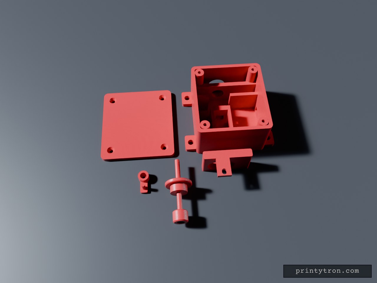
v1 Servo-Release Cable Lock with Servo Arm
Servo-operated cable lock for a paddleboard rental system. A printed servo arm fixes to the servo shaft with a top-mounted screw and drives a sliding keyhole plate that releases the cable terminal. Parts: housing, service cover, release slide, one-piece cable unit, servo arm Servo arm: 9 mm hub with a 5.2 mm shaft socket, M2 screw hole and head recess on top Arm reach: 9.5 mm drive pin radius, engaging the slide yoke slot Slide travel: 9 mm, spring-returned to locked Magnet: 6 x 3 mm coin magnet pockets in terminal tip and wall holder Print: PETG or ASA, 4+ walls, arm printed hub-up Not load-tested; prototype grade
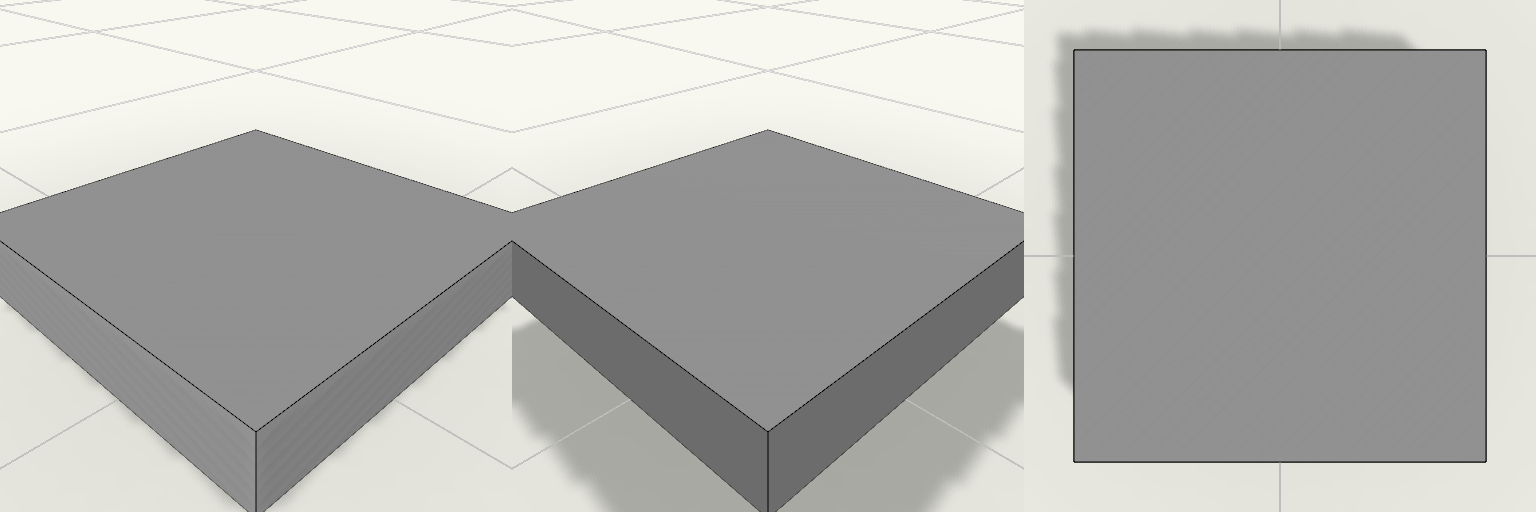
5 x 5 x 1 mm Square Block
A plain square block measuring 5 mm by 5 mm by 1 mm, flat on the bed and ready to print. Remix hooks Footprint: 5 x 5 mm is the starting value. Change it to make a tile, spacer or shim. Thickness: 1 mm is about five layers at 0.2 mm. Raise it for a sturdier piece. Edges: Add a small chamfer or rounding for a softer look. Keep it under 0.5 mm at this size. Pairs with: Use it as a test cube for tolerance checks, or as a base for a hole, text or a peg.
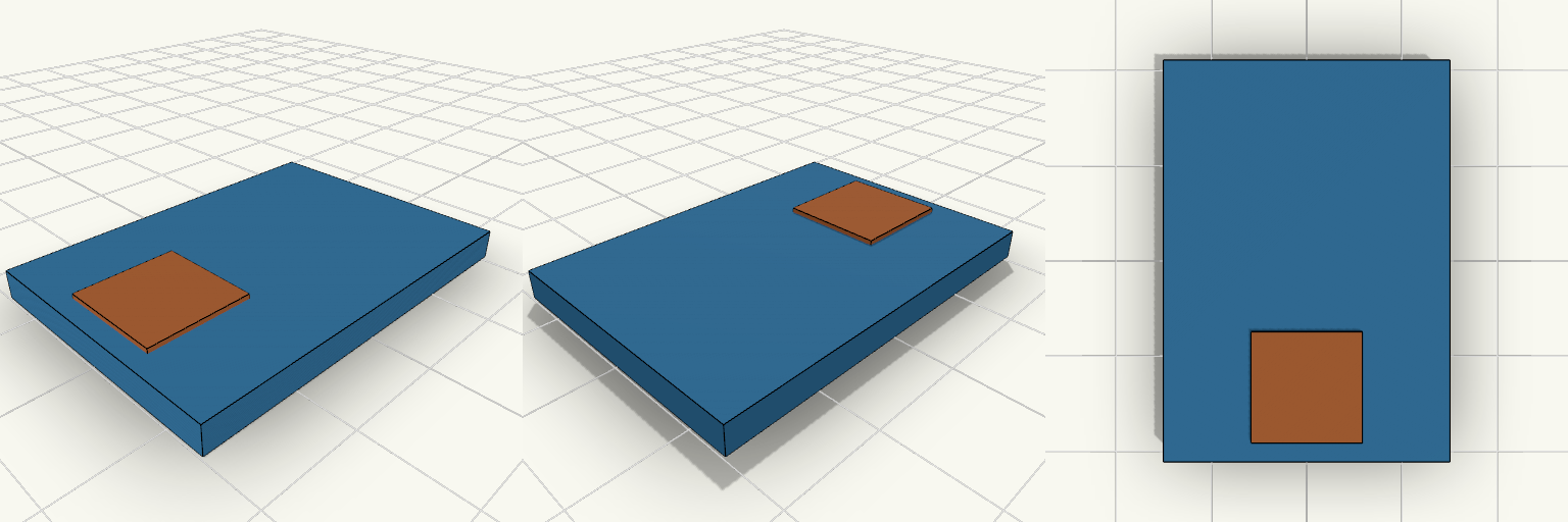
Plate With Offset Square Pad
A flat 28.5 × 40 × 3 mm plate with an 11 × 11 mm raised square pad, 0.5 mm thick, centered in X and set 2 mm from the Y- edge. Remix hooks Pad thickness (0.5 mm): a multiple of your layer height keeps the pad clean. 0.5 mm is about 2 or 3 layers. Pad offset (2 mm from the Y- edge): move it along Y to centre it or push it to the other edge. Plate length (40 mm): the pad is 11 mm, so any length above roughly 15 mm still holds it. Pairs with: a label, a sticker, or a second pad in a different colour for a multi-colour swap.
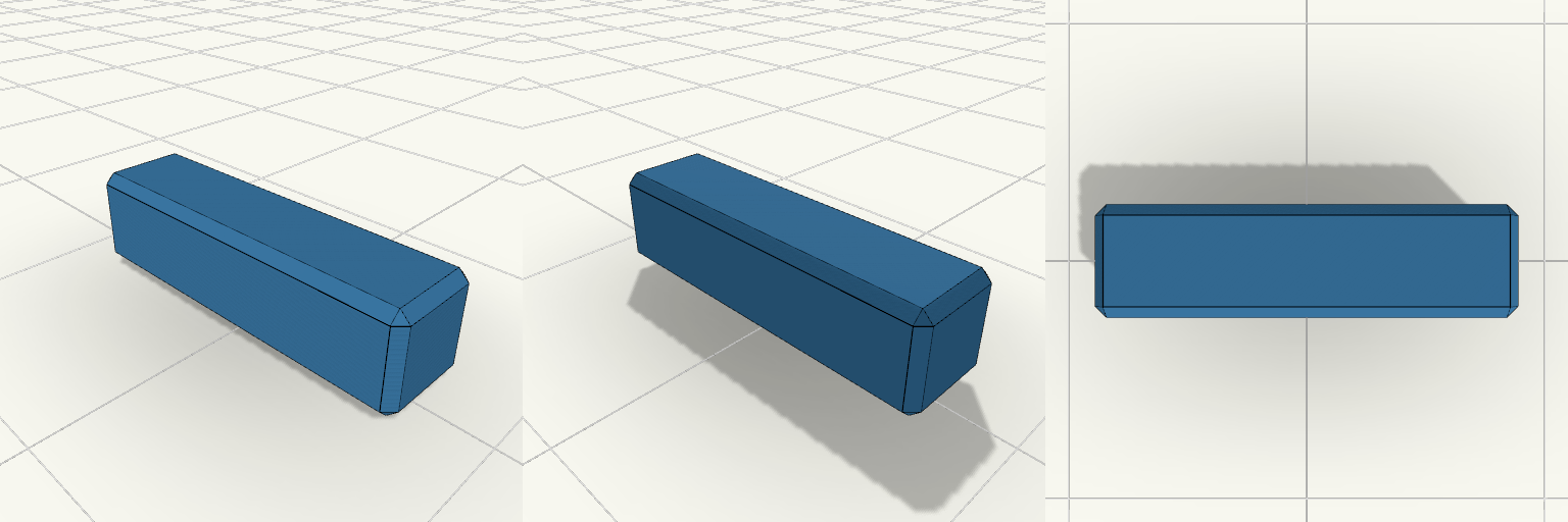
Small Block 15x4x4 mm
What it's for A small solid block for use as a spacer, shim, test piece or placeholder. Dimensions Length: 15 mm (X) Width: 4 mm (Y) Height: 4 mm (Z) Edges chamfered 0.4 mm Remix ideas Add a through hole for a screw or string. Increase the chamfer for a softer look. Engrave a label on the front face.
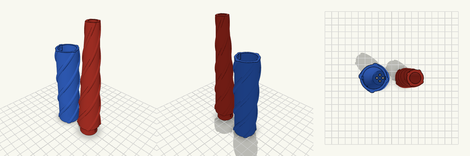
Zauberstab final
What it's for Zweiteiliger Zauberstab aus Griff und Spitze, gebaut für eine UV-Taschenlampe im Griff. Der Griff bietet 97 mm Innenhöhe, sodass die Lampe vollständig unterhalb des Bajonettverschlusses sitzt; die hohle Spitze lässt das UV-Licht oben austreten. Außen liegt ein glatter Kern mit vier runden, spiralförmig aufgelegten Teigsträngen, die wie um den Stab gelegte Teigbahnen wirken. Ein innenliegendes Bajonett mit Rastnocke hält die Teile bündig zusammen und sichert gegen unbeabsichtigtes Aufdrehen. Vier Bodenlöcher im Griff erlauben den Zugang zum Druckknopf der Lampe. Dimensions Griff: 99 mm hoch, 97 mm Innenhöhe, Innen-Ø 21,8 mm; Lampe sitzt unterhalb der Bajonettnut. Spitze: 135 mm inkl. Zapfen; Lichtkanal von 18 mm unten auf 9 mm oben; Wand im Bajonettbereich mindestens 1,5 mm. Außen: glatter Kern Ø 26,4 mm; vier Stränge unten ca. 5 mm breit und 1,4 mm hoch, nach oben ca. 2,5 mm breit und 0,7 mm hoch; größtes Außenmaß ca. Ø 29,2 mm. Bajonett: innenliegende Nut im Griff, Nasen an der Spitze, Rastnocke; Einführschlitz bis zur Oberkante; Muster auf die 45°-Endstellung abgestimmt. Boden: vier Löcher Ø 3,75 mm, enger zur Mitte gesetzt. Print notes Griff und Spitze werden getrennt gedruckt und über den Bajonettverschluss verbunden. Die Außenkontur ist glatt ausgelegt; das Relief der Teigstränge liegt als aufgesetzte Struktur darüber. Für eine saubere runde Außenwand ist eine feine Auflösung sinnvoll. Die Rastnocke ist als spürbarer Widerstand ausgelegt; je nach Drucker und Material kann der Eingriff straffer oder weicher ausfallen. Remix ideas Anzahl der Stränge oder Windungszahl über die Höhe ändern. Strangquerschnitt dicker für kräftigeres Relief oder dünner für eine glattere Oberfläche. Griffhöhe und Lichtkanal an eine andere Taschenlampe anpassen. Rastnocke stärker oder schwächer auslegen.
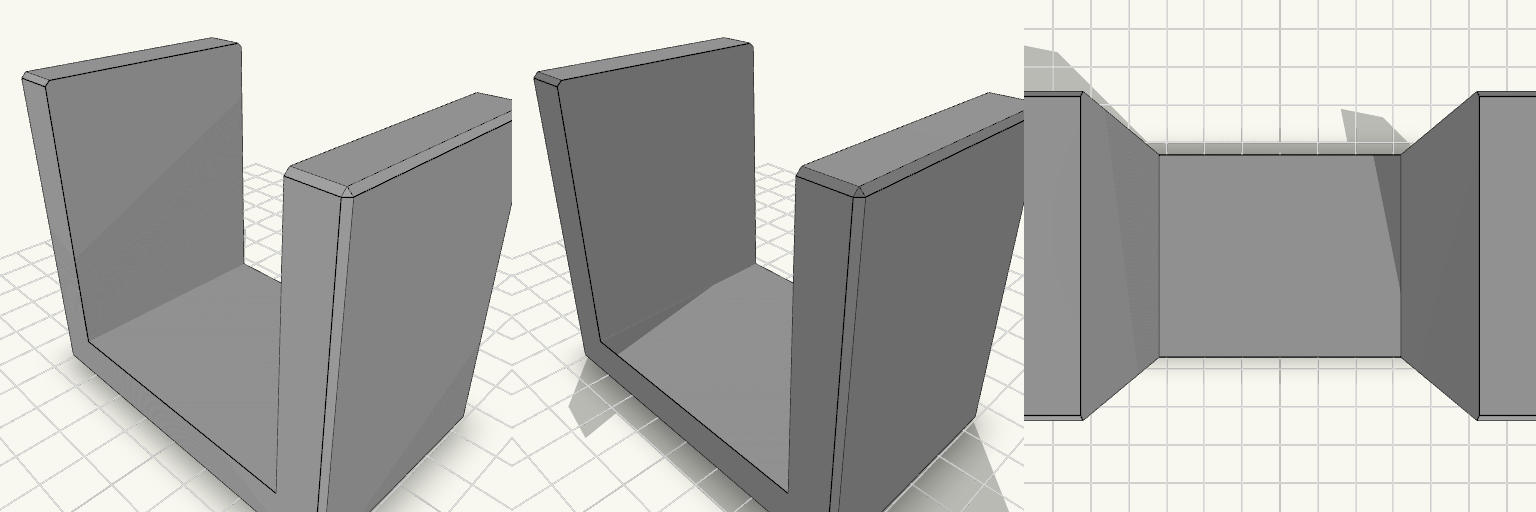
U profilis, 60 mm tarpas, aukštos sienelės
U formos laikiklis, kuriame detalė neslysta į šonus: 60 mm tarpas tarp sienelių, 10 mm sienelės ir dugnas, 50 mm pagrindo plotis. Matmenys Vidinis tarpas: 60 mm Sienelių ir dugno storis: 10 mm Sienelės virš dugno: 60 mm (pailgintos 50 mm) Bendras dydis: 80 × 50 × 70 mm Spausdinimas: dugnu ant stalo, atramų nereikia