Samsung S24 Case Blank (ITAY)
Created 1 months ago
Description
Standard phone case blank featuring a custom typography deboss on the rear face.
- Fits: Standard modern handset blank (currently S24 dimensions)
- Customization: "ITAY" carved 1.2mm deep into the back plate using Pacifico script
- Orientation: Text is mirrored in the design file so it reads correctly when viewing the outside back of the printed case.
Check your specific handset dimensions before printing, as this uses a baseline placeholder footprint.
Images
More like this
Explore more in Desk & Tech →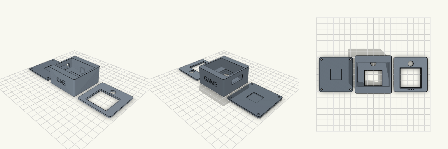
Lockdown — Dev Board Case With Camera Eye
Lockdown is a three-part enclosure for a Freenove ESP32-S3 WROOM CAM board with a 35.5 × 33.5 mm display. The front bezel turns the screen into a face, with a 9.6 mm camera eye above the window. The side wall carries one wide cable opening, so USB-C plugs and cables pass straight through the housing. Features 58 × 60 mm footprint across chassis, back cover and bezel Screen pocket with a support ledge and a flex-cable opening 9.6 mm camera bore lined up with the bezel eye Single 26 × 9 mm cable pass-through on the +X wall, raised for a high-mounted board Four M3 screws from the back Embossed-in END and GAME text on the end walls Print notes Print the three parts flat on their backs. PETG works well.
Info Orbs 1.28in Five-Display Case
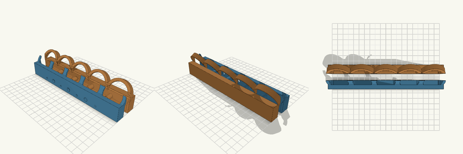
Two-part case for an Info Orbs build: five 1.28in round TFT displays across the top, a hollow base for a 200 mm controller board, and three push buttons in the front wall. The Front Half and Back Half join with four M3 screws running front to back, with heat-set inserts in the back half. Both halves print flat on their cut faces. What it fits Five 1.28in round TFT displays on 40 mm centres, tilted back 30°, with 42 mm outer housings, 39.5 mm PCB pockets and 33 mm windows. The scalloped top edge follows the rims of the displays instead of running as a plain box. A 200 mm board, including a large Arduino section. Interior space is 196 × 24 × 35 mm, so there is about 3 mm of slack all round the board. Three 6 mm tact-switch caps in 7 mm front-wall holes at −40, 0 and +40 mm. Four M3 screws at x = −10, 25, 60 and 92 mm: 3.4 mm clearance holes in the front half, 4.2 mm heat-insert holes 9 mm deep in the back half. Check before printing The screw positions assume the Arduino's 15–70 mm span is measured from the left (−X) end of the board, which puts it at x = −85 to −30 mm and keeps the nearest screw about 20 mm clear. If that span is measured from the right end, mirror the screw holes before printing. The screw bosses sit at floor level and run front to back, so they pass under the board — confirm the board clears them. The outside measures 200 × 30 × 40 mm with 3 mm walls and floor. That is not 200 × 30 × 25 mm as first specified, so check your electronics against the larger figure. Known limitations There is no internal switch mount. The tact switches must be glued or wired in place. The button holes suit 6 mm tact-switch caps, not 12 mm panel-mount buttons.
Case ESP32 + LoRa com Display e Cooler
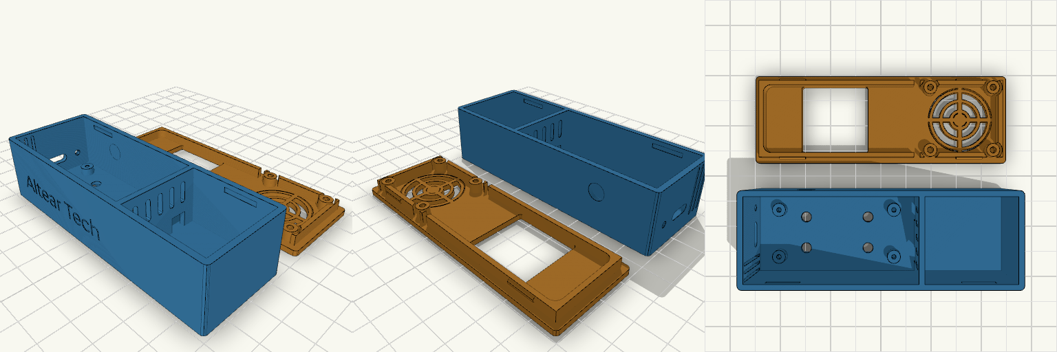
Case compacto para ESP32 e módulo LoRa SX1278, com tampa de encaixe por pressão, janela para display TFT 1.44" e cooler na tampa. Ganchos para remix Altura interna (IH = 21 mm): altura total de 24 mm. Aumente se o LoRa ficar justo. Furação do cooler: quadrado de 24 mm com pinos de 5 mm e furo de 2,4 mm. Ajuste para outro tamanho de cooler. Janela do display: 26 × 26 mm na tampa. Combina com um suporte interno para o módulo. LoRa: sem canaletas internas. Dá para adicionar suportes na medida da sua placa. Ranhuras inferiores: duas ranhuras de 4 mm para cabos entre as placas.
Octobay — 5.25" to 3.5" Drive Cage
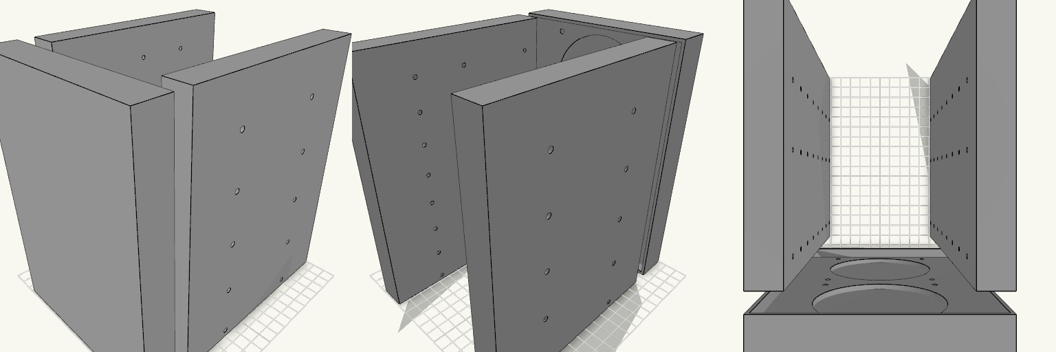
Octobay turns a five-bay stack of half-height 5.25" slots into room for eight 3.5" drives, and adds a 25 mm front cage that carries two 92 mm fans. The outer side faces take M3 heat-set inserts, so the whole cage screws into the case's 5.25" rails instead of resting on them. Everything is one printed part: the drive stack, the side mounting blocks and the fan cage print as a single body. Because the fans close off the front, drives now load from the back. The fan cavity behind the grille is hollow, so air still passes through to the drive stack. Dimensions Overall: 145 mm wide × 197.5 mm deep × 205.5 mm tall Fits: five half-height 5.25" bays Holds: eight 3.5" drives, stacked vertically Drive channel: 102.6 mm wide — 1 mm of play around a 101.6 mm drive Mounting 20 insert holes, 10 per side, for M3 heat-set inserts — 4.2 mm across and 6 mm deep Two insert holes per bay, at 41.3 and 117.5 mm from the front, 6.35 mm above each bay floor Solid blocks sit behind each hole to give the inserts something to bite into Three M3 screw holes per side per drive, at 14, 76.6 and 117.6 mm from the front Cross ribs sit clear of the screw holes so a screwdriver can reach every fastener Fan cage Two 92 mm fans, stacked vertically on the 25 mm front section 88 mm fan openings with 4.4 mm screw holes on the standard 82.5 mm square pattern Hollow cavity behind the fans feeds air to the drive channels Print notes Drive channels are open at the back, top and bottom, and the gaps between the inner and outer side walls are open for cable routing. Screw and insert positions and the 205.5 mm height follow common 5.25" bay standards; they have not been checked against a specific case, so measure your bay rails and drives before printing.
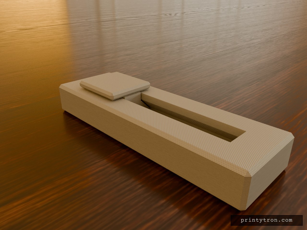
Fidget Slider Toy, Captive Print-in-Place
A fidget slider that prints already assembled, so there is no loose weight to lose and nothing to glue. The slider is captured in an enclosed dovetail track and cannot fall out. It runs 40 mm end to end and clicks at each stop instead of rolling freely. What it does Slides back and forth along a closed track in an 80 x 25 mm body. A small bump on the track floor at each end of travel drops into a dimple under the slider and gives the click. The dovetail profile holds the slider down, so it cannot lift out of the rails. Numbers that matter Body: 80 x 25 x 11 mm, with the slider top reaching 14 mm. Slider: 20 mm long, 18 mm wide cap. Travel: 40 mm. Clearance between slider and track: 0.4 mm per side. This is what lets it move after printing. Click bump: about 0.6 mm of interference against the 0.4 mm gap. Reduce the bump height if it feels too stiff. Printing Print flat, body base down, with no supports needed inside the track. Use a well-tuned printer. A 0.4 mm gap fuses easily if the flow is too high. After printing, work the slider back and forth a few times to break any thin bridging between the slider and the rails. Two colours show as separate parts in the preview, but the print is one job.
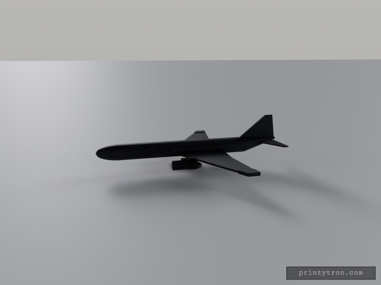
Virgin-Rot-Weiß: Boeing 777 Standmodell
Virgin-Rot auf Weiß: Der weiße Rumpf mit rotem Bauchstreifen, das rote, gepfeilte Seitenleitwerk und die roten Triebwerke an den Flügeln bringen den Virgin-Atlantic-Look auf den Tisch. Die Boeing 777 steht als Standmodell mit gewölbter Nase, hochgezogenem Heck, blauen Fensterreihen und schrägen Cockpitscheiben; auf beiden Rumpfseiten steht „virgin atlantic“ in roter Schrift. Einläufe und Ständer sind weiß gehalten. Was dran ist: Maßstab etwa 1:320 – rund 230 mm lang und 200 mm Spannweite Gepfeilte Flügel mit roten Spitzen, Triebwerke an Pylonen mit weißen Einläufen Fensterreihen und Cockpitfenster in Blau, roter Bauchstreifen und Schriftzug „virgin atlantic“ Kein Fahrwerk – ein weißer Ständer trägt das Modell Farben getrennt wählbar: Weiß für Rumpf, Flügel, Höhenleitwerk, Einläufe und Ständer; Rot für Leitwerk, Triebwerke, Spitzen, Streifen und Schrift; Blau für die Fenster