Scatola Bticino Matix Flangiata
Created 1 months ago
Description
Scatola esterna su misura per alloggiare un interruttore della serie BTicino Matix, progettata per l'accoppiamento con un pannello alimentatore.
- Sede frutto: Foro centrale 22.5 x 45.0 mm ottimizzato per incastro a scatto Matix.
- Fissaggio asimmetrico: Flange sfalsate per adattarsi alla struttura (interasse 40 mm, dislivello Z 26 mm).
- Passacavi: Doppia uscita posteriore da 8 mm.
- Stampa: Coperchio ottimizzato per stampa a faccia in giù senza supporti.
Images
More like this
Explore more in Home & Fixtures →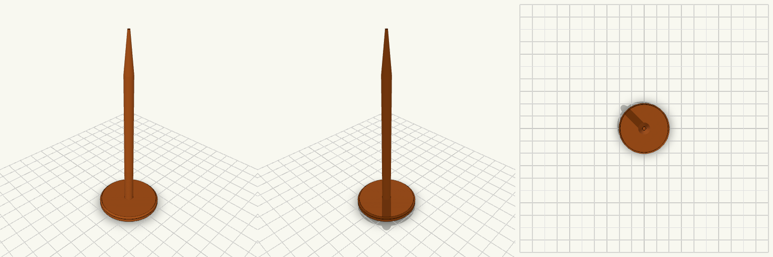
Charging Station Marker Nail
A ground marker nail for holding the position of a robot mower charging station while the charger is stored for the season. It is pushed into the soil where the charger's screw sits in summer. The nail has a wide, flat 40 mm head that stays visible at ground level, a slim 6 mm round shaft, and a tapered point for easy insertion. It prints head-down, so no supports are needed. Head: 40 mm diameter, 4 mm thick, chamfered edge Shaft: 6 mm diameter, about 90 mm long Tip: tapers to a point over 25 mm Overall length: about 119 mm Prints without supports
Draining Sleeve Foot for a Laundry Hamper Leg
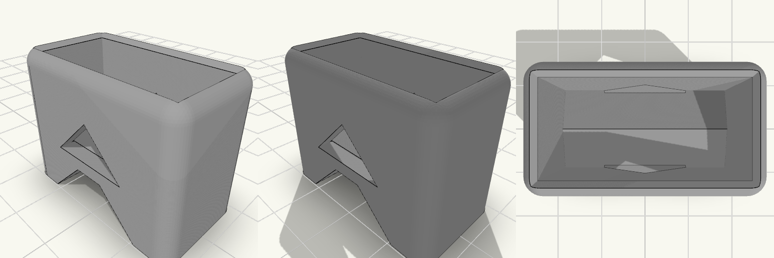
The wood at the bottom of a hamper leg is the first thing to go: it stands in whatever puddle the bathroom floor collects, drinks it up, and goes soft until the basket slumps and rocks. This sleeve slides onto the end of one rectangular wooden leg, holds the wood about 9 mm clear of the floor, and slopes its pocket floor so splash water runs out the sides instead of sitting in there against the wood. What it does Pocket: 31 × 15 mm inside, sized exactly to the leg with no added play — that measurement already accounts for clearance. 15 mm deep at its shallowest point, the centre ridge, and deeper toward the sides where the floor falls away. Stand-off: a single arched cut runs the full depth of the underside, leaving two flat feet that hold the leg about 9 mm off the floor. Overall height is about 27 mm. Drainage: the pocket floor is a shallow ridge sloping down to both long sides, with one 16 mm slot through each long wall at the low edge. Water leaves sideways, and the slot bottoms sit 10.5 mm above the floor, so no opening rests in the wet. Each slot is pointed at the top rather than flat-roofed, which is what lets it print clean. Shape: 1.2 mm chamfer at the opening to get it started over the wood, 3 mm rounding on the vertical and top edges so it doesn't snag a mop or a bare toe. The bottom edges are left sharp so they sit flat on the bed. Printing it Print in PETG with the sleeve opening facing up and the two feet on the bed — no supports anywhere. The arch sides are 45°, so the only bridge is the flat strip about 6 mm across the roof of the arch. The finished part measures roughly 36 × 20 × 27.2 mm, walls 2.5 mm thick. A plain matte finish in white, grey or black sits well in a bathroom. A zero-clearance pocket is tight in PETG. Check the leg with calipers before printing if the wood looks swollen or tapered — if it won't slide on, the pocket wants a few tenths opening up.
Beam Clamp Clothes Hanger with Side Hook
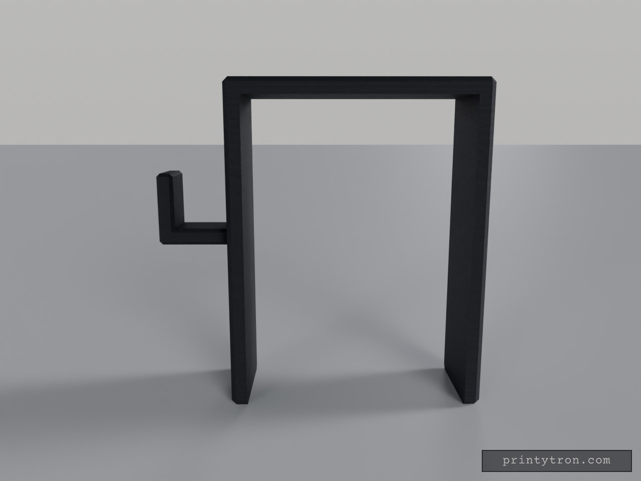
What it's for A saddle that drops over the top of a support beam and turns it into a place to hang clothes. The inverted U-shaped channel grips the beam from above, and a hook projects from one side with an upturned tip so hangers and garments stay put. Beam Saddle — the U-shaped body that slides down over the beam Hook — the side arm with an upward tip for hangers or coats, set at mid-height of the saddle Both areas print as a single piece; nothing needs assembling. Dimensions Saddle opening: 68 mm inner width, sized for a beam of that width Overall saddle: 78 × 30 mm footprint, 100 mm tall Channel: 95 mm deep, with 5 mm thick walls Hook: 22 × 15 × 22 mm, mounted at mid-height so its tip stays inside the 100 mm envelope The 95 mm channel is generous for a shallow beam — the saddle simply sits lower on it, and the hook rides down with it. Print notes Print the saddle opening facing up so the channel needs no supports A few extra perimeters on the hook help when it carries heavy coats Scale the opening slightly if your beam measures over 68 mm Remix ideas Lengthen the hook for bulky winter coats Shorten the legs for a shallower beam and keep the height with a taller top plate Add a second hook on the opposite side for more hanging room Add a small lip or screw hole at the bottom of the saddle to stop it shifting sideways
U-Turn — Zweiteilige 180°-Schlauchführung
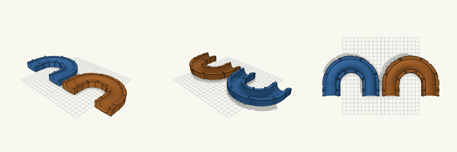
U-Turn ist eine zweiteilige 180°-Schlauchführung, die einen Schlauch mit 25 mm Außendurchmesser in einem gleichmäßigen Bogen umlenkt, sodass Ein- und Auslauf parallel nebeneinander in dieselbe Richtung zeigen. Statt Schrauben oder Muttern halten handelsübliche Kabelbinder die beiden Hälften zusammen: Mehrere außenliegende Nuten laufen um den gesamten Querschnitt, sodass die Binder nicht seitlich abrutschen und nicht in den Schlauchkanal hineinragen. Die flache Außenseite liegt beim Druck unten, die Nut zeigt nach oben — dadurch kommen beide Hälften ohne Stützmaterial aus. Maße Schlauchkanal: 26 mm Innendurchmesser für einen Schlauch mit 25 mm Außendurchmesser Bogen: exakt 180°, Biegeradius 50 mm zur Mittellinie, Mittellinien 100 mm auseinander Gerade Ein- und Auslaufstrecken: je 30 mm, an den Enden auf etwa 33 mm aufgeweitet Wandstärke: 4 mm; Querschnitt 42 mm breit, jede Hälfte 17 mm hoch Kabelbindernuten: 5,2 mm breit und 1,5 mm tief für 4,8 mm breite Binder; Restwand an der dünnsten Stelle 2,5 mm Aufbau Beide Hälften verlaufen über den gesamten 180°-Bogen und tragen je eine halbrunde Nut, die zusammengesetzt einen geschlossenen, kreisförmigen Kanal ergibt. Die Hälfte mit den Zapfen trägt Zapfen von 5 mm Durchmesser und 4 mm Höhe, die Gegenhälfte passende Aussparungen von 5,4 mm Durchmesser — das ergibt ein Montagespiel von 0,2 mm je Seite. Die Zapfen sitzen beidseitig des Kanals, sowohl auf dem Bogen als auch an den geraden Endstücken, und verhindern ein seitliches Verrutschen. Montage Die Hälfte mit den Aussparungen umdrehen, auf die Hälfte mit den Zapfen setzen und andrücken. Anschließend Kabelbinder durch die Nuten führen und festziehen: fünf Nuten verteilen sich gleichmäßig entlang des U-Bogens, je zwei sitzen an den geraden Endstücken. Druckhinweise Beide Hälften werden getrennt gedruckt und anschließend zusammengesteckt; die Kabelbinder übernehmen die Fixierung. Der Kanal ist an beiden Enden großzügig abgerundet, damit der Schlauch ohne Knickstellen ein- und ausläuft.
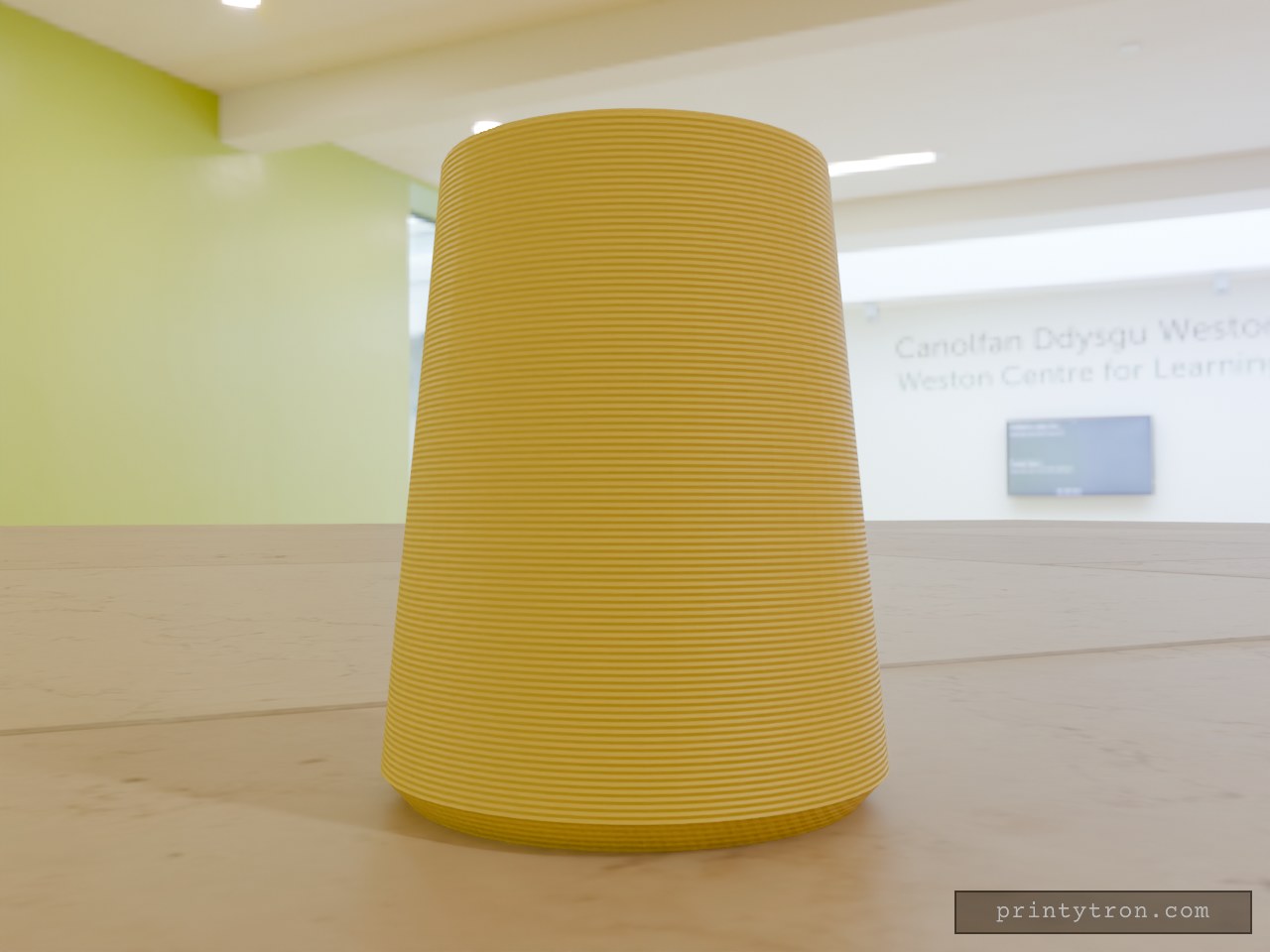
Cabinet Handl Bumper
A cabinet handle end that slams into the door or wall now has a cone-shaped TPU bumper to take the hit. The bumper slides over the handle end and stays put on an 11.8 mm blind hole. Key numbers Height: 32 mm Base diameter: 26 mm, with a 1.5 mm 45° chamfer on the bottom edge Narrow end diameter: 20 mm Hole: 11.8 mm diameter, 24 mm deep, opening at the narrow end Print: TPU, base down, no supports needed
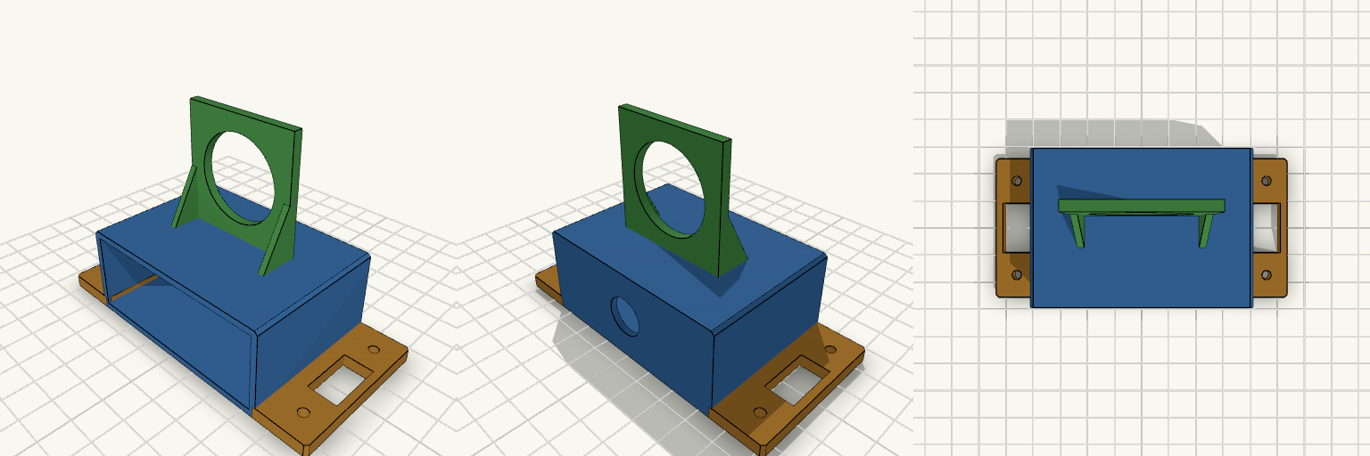
Scatola con porta voltmetro per montaggio laterale
Scatola rettangolare a fondo aperto da avvitare su un mobile, con un pannello verticale sul tetto per il voltmetro. Pensata per stamparsi senza supporti e con poco filamento. Corpo: 70×30×50 mm, pareti da 2 mm Foro da 13 mm sul tetto per i cavi, foro da 29 mm nel pannello voltmetro 40×40 mm Rinforzi triangolari ai lati del pannello, senza sporgenze da sostenere Due alette di fissaggio con fori da 3,4 mm (viti M3), alleggerite da una finestra centrale Stampa: alette appoggiate sul piano, nessun supporto necessario nei rinforzi