Tapered Silicone Depth Stopper
Created 1 months ago
Description
A clean, rotationally symmetrical collar designed to act as a physical limit stop. Built specifically to seat around a cylindrical silicone component, its continuous taper drops from an 80mm base down to a 55mm neck while maintaining a rigid 3mm wall.
Design Notes
- Smooth Contact: Fully rounded 1mm radii on both the upper and lower lips prevent the hard plastic from digging into softer silicone.
- Unbroken Profile: A simple, continuous exterior taper with no interruptions or decorative elements.
- Print-Ready: Sits flat on its wide base and requires no supports, hardware, or post-processing.
Photos
Technical views
More like this
Explore more in Workshop & Tools →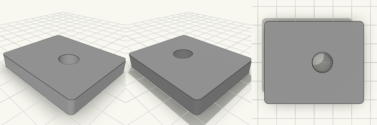
Elliptical Pedal Insert 48x40 Offset Hole
What it's for Central reinforcement insert for an elliptical trainer pedal, bonded into the damaged opening. Flat top, ribbed underside. Dimensions Base: 48 × 40 × 7 mm, rounded corners Through-hole: 10 mm, centered at 24 mm along the length and 4 mm toward the top edge from the width center 18 mm boss around the hole, 5 ribs to a 3 mm frame Remix ideas Change the hole offset for a different pedal Add or remove ribs Thicken the frame for heavier loads
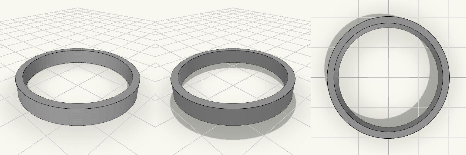
Кольцо 37/33 мм, толщина 5 мм
Простое круглое кольцо-втулка с ровными торцами. What it's for Прокладка, проставка, втулка или заготовка для переходного кольца. Печатается лёжа, без поддержек. Dimensions Наружный диаметр: 37 мм Внутренний диаметр: 33 мм Толщина стенки: 2 мм Высота (толщина кольца): 5 мм Remix ideas Добавить фаски на кромках. Увеличить внутренний диаметр на 0,2–0,4 мм для посадки с зазором. Добавить выступ или паз для фиксации.
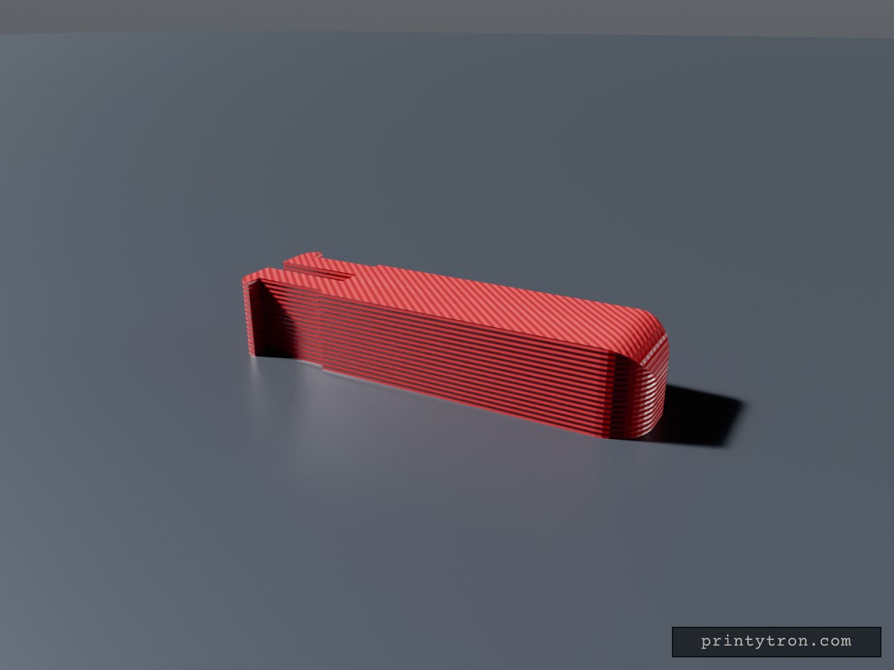
sink drain lever, G*b*rit
A small rectangular block, 26 mm overall, made of a 20 mm body and a 6 mm slotted end section. A narrow slot is cut into the 7.5 mm end face: 1.5 mm wide, running 6 mm into the length and through the full 5 mm height, so it reads as a thin open channel down that end. The slotted 6 mm keeps the full 7.5 mm width, while the rest of the body is narrowed to 6.5 mm, so a 1 mm shoulder sits on each side where the two sections meet. On the two flat side faces — not on the long corners — a straight rectangular step is cut 1 mm deep over the full 5 mm height. It starts 6 mm in from the slotted end and stops 1 mm short of the end face, so the last millimetre keeps its full width and a small square notch is left at the end. There is no angle anywhere in this cut. The far end from the slot is rounded: both vertical corners and the top edge there carry a 2.4 mm radius, blending into one soft rounded end — about as much as a 5 mm tall block can take before the curve meets itself halfway. The outer corners at the slotted end carry a small 0.9 mm radius; the side steps and the notch itself stay sharp, and the remaining top and bottom edges stay square. It works as a spacer, shim or register that a thin rib or plate edge drops into, with the side step giving that end a shoulder to seat against. Starting values Overall length: 26 mm — a 20 mm body plus the 6 mm slotted end section Body cross-section: 6.5 × 5 mm; the last 6 mm at the slotted end is 7.5 × 5 mm (1 mm shoulder each side) End slot: 1.5 mm wide, 6 mm deep along the length, through the full 5 mm height, centred Side steps: 1 mm deep on both flat side faces, constant depth, running full height, starting 6 mm from the end and ending 1 mm before the end face Far-end vertical corners and top edge: 2.4 mm radius, rounded Slotted-end outer corners: 0.9 mm radius; side steps and notch corners sharp Prints as one piece, no supports needed for any of the features above Remix hooks Body length is the free dimension. The 20 mm is the span between the rounded end and the start of the slotted section — stretch or shorten it to set the gap, and nothing else about the part has to change. The 6 mm slotted section is the fixed end, so all the length adjustment happens at the plain end. The width step is the fit dial. The 6.5 mm body and the 7.5 mm slotted end are two independent numbers: match the narrow body to the channel it slides into and the wider end to whatever it shoulders against. Equalising them removes the shoulder entirely and gives a plain constant-width block. Where the step falls. The 7.5 mm section currently runs the last 6 mm, tied to the slot depth; move that boundary to change how much of the part is full width. Slot width is the tightest tolerance. At 1.5 mm it takes a thin rib, sheet-metal edge or card; resize it to suit whatever it has to straddle, and remember a printed slot usually needs a little clearance over the nominal thickness. Slot depth sets the character. At 6 mm it is a deep open channel relative to the 26 mm part; shorten it to a millimetre or two and it becomes a shallow locating register instead. Side step depth. At 1 mm the relief is shallow and forgiving; go deeper for a part that shoulders harder against a pocket wall, or take it to zero for plain flat sides. The 1 mm land before the end face is what forms the notch — widen or remove it to change how the part locks against a shoulder. The far-end radius is already near its ceiling. 2.4 mm is close to the limit on a 5 mm block, so going rounder means growing the height, not the radius. Drop it to 1.5 mm for a snugger square look, or zero for a sharp end. Slotted-end radius is the tight one. 0.9 mm is limited by the short 1 mm end tab; widening that land is the way to buy room for a rounder corner there. Shape of the relief. Swapping the flat step for a ramp, or cutting the corners instead of the flat faces, turns this into a lead-in wedge or a chamfered block. Through vs. blind. The slot cuts the full height, so it is visible from both the top and bottom faces; make it blind and you get a closed-bottom channel. Obvious pairings. A matching 1.5 mm rib or plate edge for the slot to register against, or a mirrored second block so the two slots face each other and trap a thin part between them.
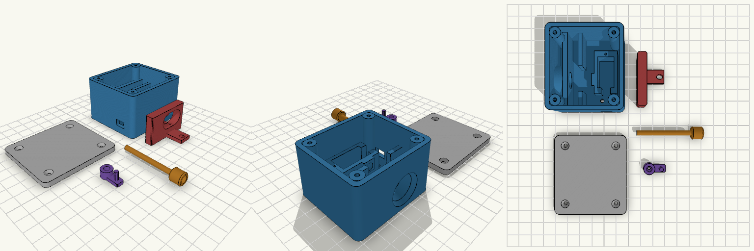
final cable lock sideways servo
Servo-operated cable lock for a paddleboard rental system, laid out as five separate printed parts: housing, service cover, release slide, cable unit and servo arm. The release slide prints top face down, so the yoke arm forms the first layers and needs no supports. The cable unit lies with its round head on the bed. Printer: Bambu Lab A1 mini, PETG or ASA Cable unit: 4 mm rod with 10 mm round terminal head and a magnet pocket in the tip Slide: 7 mm locking slot, 14 mm release hole, 9 mm travel Servo: 9 g micro servo, lead exits at the front end Export: set part to housing, cover, slide, cable or arm Untested: the design has not been load-tested and is not waterproof
90 Degree Corner Clamping Jig
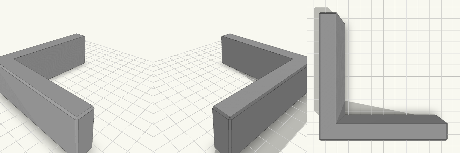
An L-shaped corner jig that holds two boards at a true 90 degrees while glue sets. It is made for picture frame joints, where a loose corner tends to drift into a parallelogram. Each arm has a channel that cradles a board up to 20 mm thick, and the two channels meet at a square inside corner. The 12 mm walls hold their shape under clamp pressure, and the outer edges are chamfered for a clean, easy-to-handle part. Fits stock up to 20 mm thick Square 90 degree inside corner 90 mm arms, 30 mm tall Clamp slots on each arm for squeezing the boards into the corner Flat base prints without supports Print it in PETG or PLA with several perimeters for stiffness. Keep glue off the channel walls, or line them with tape so the jig does not bond to the work.
living room plinth
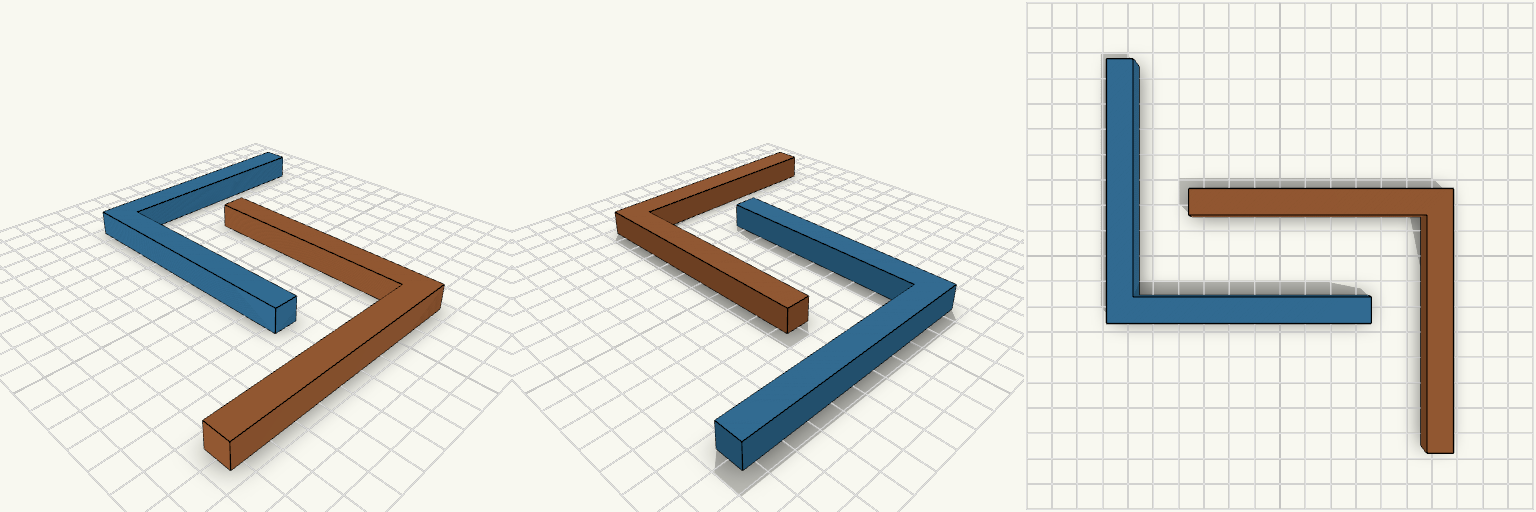
Two 100 × 100 mm L-sections, 10 mm leg width and 10 mm thick, laid flat and nested together to save print-bed space. Fit and layout One piece sits normally; the other is flipped onto its back and turned so the two interlock with a 1 mm gap. Combined footprint: about 111 × 111 mm. Check before printing: the 1 mm gap needs a bed that prints cleanly at that spacing; widen it if the pieces fuse. Not a fit for beds under 115 mm square.