Touchscreen-Gehäuse mit Klappfuß STL
Made by RagebaitedMaster
Created today
Description
Schlichtes Gehäuse für das 7-Zoll-Display Pollin LS-7T, im Stil eines kleinen Werkstatt-Terminals. Hinten sitzt eine abnehmbare Rückwand mit Lüftungsschlitzen. Der U-förmige Standfuß ist ein eigenes Bauteil und liegt zum Drucken flach neben dem Gehäuse.
Hinweise
- Standfuß separat gedruckt, ohne Stützen druckbar
- Befestigung am Gelenk mit je einer M5-Schraube samt Mutter
- Kabelschlitz über die volle Breite, 10 mm hoch
- Platinen-Abstandshalter im Raster 122 × 79 mm (bitte gegen die Platine prüfen)
Images
More like this
Explore more in Desk & Tech →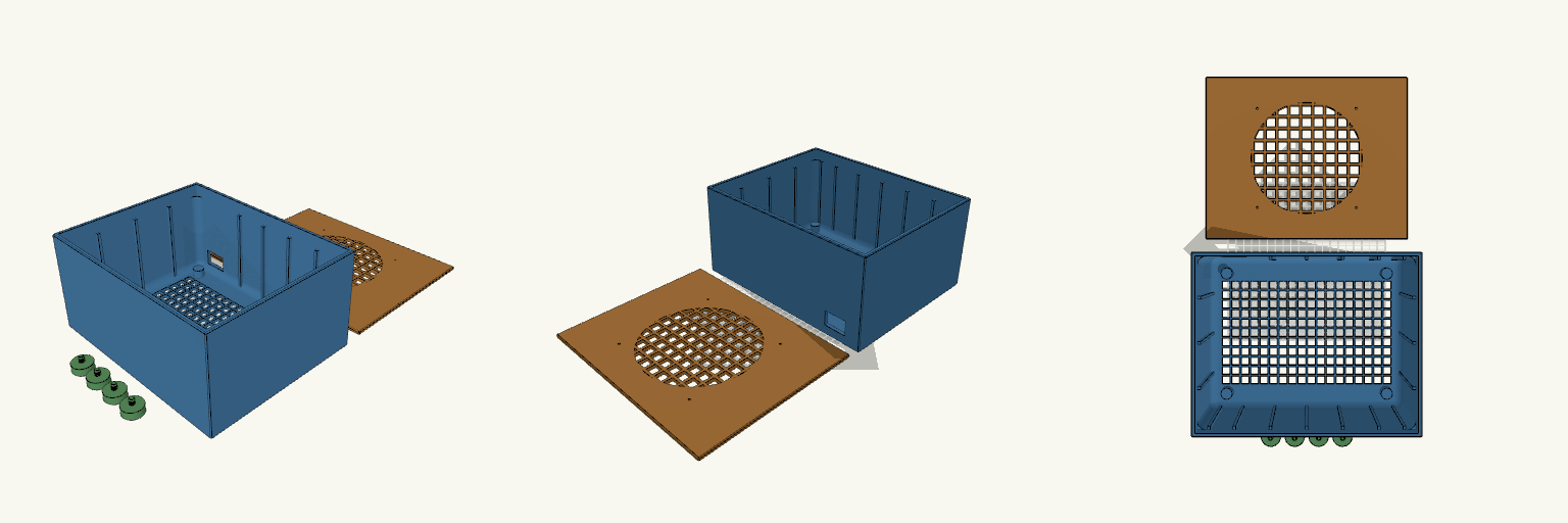
Mini-Server-Box with Feet, Lid and Fan (more stable)
What it's for A closed-side enclosure for hiding and cooling equipment. All four side walls are solid, so the box stays dark and quiet from the sides. Airflow passes through the mesh grid in the floor and the mesh fan opening in the lid. A 30 × 20 mm cable hole in the lower rear corner lets wiring in and out, and the flat lid lifts off for access. The model prints as separate pieces: the box, the lid and four feet. The lid is a plate with a locating lip underneath that sits well inside the box, and it overhangs the walls slightly so it can never drop in. The 140 mm fan opening is filled with a square-hole grid, keeping the full opening size while adding stiffness. Each foot carries its own coarse threaded stud, so the feet screw directly into threaded holes in the floor bosses with no separate fasteners. Dimensions Box: 250 × 200 × 120 mm outside, with 4 mm walls and floor and a 242 × 192 mm cavity. Solid on all four sides, with a 30 × 20 mm cable opening in the rear wall kept clear of ribs. Wall ribs: vertical ribs on the inside faces, 3 mm thick and standing about 4 mm proud of the walls, running from the floor up to the lid recess. They are spaced about every 40 mm on the long walls and every 50–60 mm on the short walls, and stop clear of the cable opening and the foot posts. Floor mesh: sized to the narrower floor and ending where the foot posts and screw holes begin. The openings are 10 mm on a 12 mm pitch. Lid: 254 × 204 × 9 mm overall, with a 4 mm plate. Underneath, two lengthwise and two crosswise ribs, each 3 mm wide and 3 mm high, sit inside the lip so the lid still seats the same way. The locating lip follows the inner wall with roughly 5.5 mm of play per side and is 5 mm tall so it reaches into the box; its lower edge is chamfered to guide it in. Fan opening: 140 mm across, filled with a grid of 12 mm square holes on a 15 mm pitch, leaving 3 mm bars. The four fan screw holes are on a 124.5 mm square and cut through the lid plate. Check this against your actual fan before printing. Feet: four 24 mm discs, 18 mm tall including a 6 mm thick, 8 mm long threaded stud; 1.5 mm pitch, matching the threaded floor bosses. The set measures 114 × 24 × 18 mm laid out. Print notes Print the box, lid and feet separately. The wall ribs are straight verticals, so they need no supports or overhangs. The lid ribs are shallow and bridge cleanly. Print the lid lip-side up so its flat face sits on the bed and the lip rises clear of the plate. The 4 mm walls, floor and lid plate rely on perimeter count and the ribs for stiffness, so wall count matters more than infill. With walls this thin, flex will go up a little; the wall ribs matter more now. Give the floor mesh and fan grid enough perimeters to keep the bars sturdy. The threads have not been test-fitted; if the feet bind, raise the socket diameter slightly, and if they wobble, lower it. Suggested PETG settings (0.4 mm nozzle) Layer height: 0.2 mm for a clean surface, 0.3 mm to cut print time substantially; keep the first layer at 0.25–0.3 mm for adhesion. Print the feet at 0.16–0.2 mm so the threads come out clean. Wall lines: 3 lines for the box and lid with the 4 mm walls; 3 for the feet. Ribs and grid bars: 3 mm thick, so enable thin-wall detection so they print solid rather than with gaps. Top/bottom layers: 4 each at 0.3 mm layer height; 4–5 each at finer layer heights. Infill: 12–15% gyroid or cubic is enough given the nearly solid walls; raise it only if the box still feels soft. Speed: outer walls around 35–40 mm/s, inner walls 50–60 mm/s, infill 60–80 mm/s. Temperatures: 235–245 °C nozzle, 70–80 °C bed, part fan at 30–50% for good layer bonding. Use a brim on the box if corners lift. Remix ideas Add a removable filter frame behind the fan grid. Add internal standoffs or a shallow tray for mounting equipment inside. Resize or duplicate the rear cable port for thicker cable bundles. Add a second row of wall ribs for even stiffer walls with the 4 mm walls. Change the fan grid bar thickness or hole pitch to trade airflow for stiffness. Swap the floor grid for a denser or more open pattern to change the airflow.
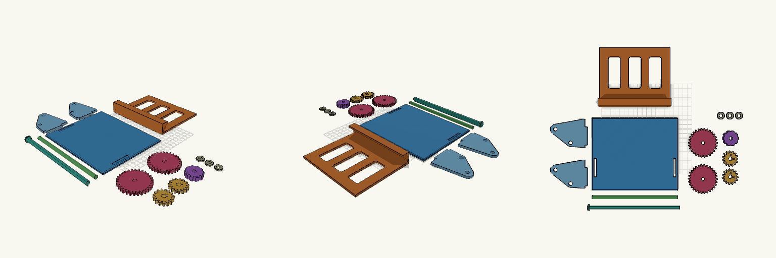
Slot-Together Geared Tablet Stand, Doogee U11
Geared tilting tablet stand for the Doogee U11, laid out as 14 separate flat pieces for printing and assembled by hand after printing. A knob on a drive shaft turns two 30-tooth gears that mesh with 15-tooth gears on the cradle, so a small knob twist tilts the cradle forward or back. Pieces Base plate: 1 Side plates: 2, with tabs that drop into slots in the base Tablet cradle: 1 15-tooth cradle gears: 2, peg into the cradle ends 30-tooth drive gears: 2, keyed to the drive shaft Knob: 1 Axle: 1, 8 mm round Drive shaft: 1, D-profile Friction-fit caps: 3 Print notes Every piece is laid flat on the build plate with no overlap. Gear pegs face up and the shaft flat faces down, so no supports are needed for the main bodies. Clearances are about 0.2-0.4 mm; adjust for your printer. Gear mesh and fit are untested; friction alone holds the tilt angle.
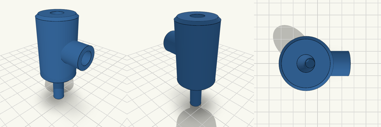
Lichtschirmhalter mit M6-Einschraubmutter und CHB1-Zapfen
Dieser Lichtschirmhalter fixiert einen Lichtschirm mit 7,5-mm-Rundschaft. Die Hülse hat 24 mm Außendurchmesser und 40 mm Höhe; ihre 7,8-mm-Bohrung lässt dem Schaft 0,3 mm Spiel. Seitlich sitzt ein Dom mit einer 8,4-mm-Aufnahme, 8 mm tief, für eine M6x8-Einschraubmutter. Eine 6,4-mm-Bohrung führt zur Schaftbohrung, sodass die M6-Schraube direkt auf den Schirm drückt. Unter der Hülse sitzt ein 7,7-mm-Zapfen, 20 mm lang, für das 8-mm-Loch am Neewer CHB1; auch hier 0,3 mm Spiel, die Kante ist angefast. Auf der Druckplatte misst der Aufbau 34 × 24 × 60 mm. Ansatzpunkte zum Weiterbauen Schaftbohrung: 7,8 mm für einen 7,5-mm-Schaft. Bei einem anderen Schirm ist das der erste Wert, der angepasst werden muss; 0,2–0,3 mm Spiel reichen aus. CHB1-Zapfen: 7,7 mm Durchmesser und 20 mm Länge für ein 8-mm-Loch. Für eine andere Halterung lassen sich Durchmesser und Länge ändern, ohne die Hülse selbst anzutasten. Mutteraufnahme: 8,4 mm Durchmesser und 8 mm Tiefe für eine M6x8-Einschraubmutter. Der Außendurchmesser streut je nach Hersteller – hier lohnt sich ein Nachmessen vor dem Druck. Mantel: 24 mm Außendurchmesser und 40 mm Höhe bestimmen Wandstärke, Domfleisch und Führungslänge. Kürzer trägt flacher auf, länger stabilisiert stärker. Paarung: Gedacht für Lichtschirme an Studioblitzen mit Bowens-Anschluss und Neewer CHB1; der Zapfen lässt sich als Aufnahme unter der Hülse weiterentwickeln.
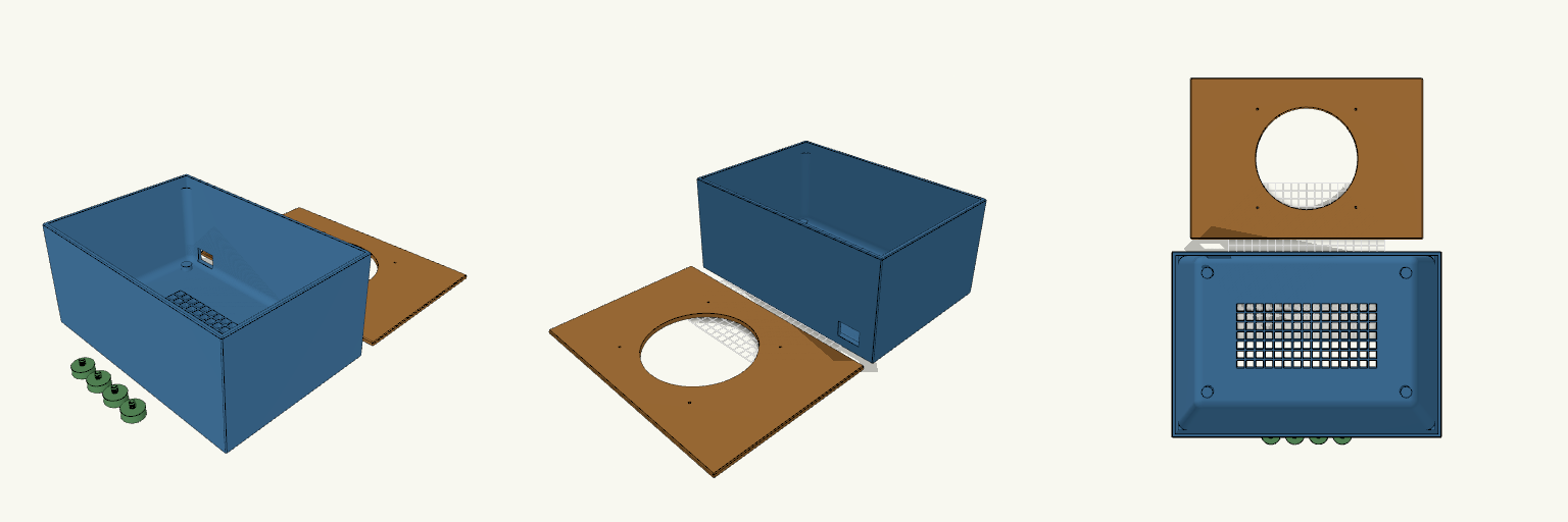
Mini-Server-Box with Feet, Lid and Fan
What it's for A solid-walled enclosure for hiding and cooling equipment. Every side wall is closed, and the only airflow path is a sturdy grid cut into the floor, so the box stays dark and quiet from the sides. A 30 × 20 mm cable hole in the lower rear corner lets wiring in and out, and the flat lid lifts off for access. The model prints as separate pieces: the box, the lid and four feet. The lid is a flat plate with a locating lip underneath, slightly larger than the box on every side so it overhangs and can never drop inside. Each foot carries its own coarse threaded stud, so the feet screw directly into matching threaded holes in the floor bosses with no separate fasteners. Dimensions Box: 290 × 200 × 130 mm, with 4 mm walls, solid on all four sides, an 8 mm floor, and a 50 mm solid border around the floor grid. The floor grid is centred on the narrower floor. The thicker floor makes the mesh bars deeper, so airflow per opening drops slightly. Inside fillets: 10 mm radius on the vertical corners and the floor-to-wall edges, stopping 15 mm below the rim. The top 15 mm stays square so the lid and its lip fit without changes. Lid: 294 × 204 mm, 9 mm overall with a 5 mm plate and underside lip; overhangs the box by 2 mm on all sides; 140 mm fan opening and four 3 mm fan screw holes at 124.5 mm center-to-center. Cable hole: 30 × 20 mm in the rear wall, set 20 mm from the left edge and 12 mm above the bottom, inside the solid section so it doesn't weaken the corners. Feet: four solid 24 mm discs, 10 mm tall, each with a 6 mm thick, 8 mm long threaded stud on top; 18 mm overall. The studs use a 1.5 mm pitch. Foot sockets: four corner bosses widened to 14 mm, with threaded holes 6.6 mm across and 11 mm deep at the same 1.5 mm pitch, giving about 0.6 mm clearance on diameter. Print notes Print the box, lid and feet separately. Print the lid lip-side up so its flat face sits on the bed and the lip rises clear of the plate. The floor grid benefits from enough perimeters to keep the bars sturdy. The threads have not been test-fitted; if the feet bind, raise the socket diameter slightly, and if they wobble, lower it. Test-fit the fan and check its screw-hole spacing before committing to a full print. Remix ideas Add a removable filter frame behind the fan opening. Add internal standoffs or a shallow tray for mounting equipment inside. Resize or duplicate the rear cable port for thicker cable bundles. Swap the floor grid for a denser or more open pattern to change the airflow.
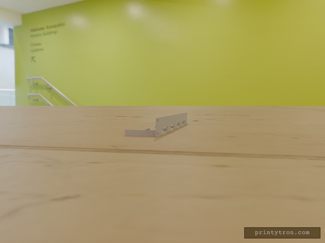
Four-Board 1U Rack Mount for Orange Pi 5 Pro
A 1U, 19-inch rack mount for four Orange Pi 5 Pro boards. The front panel fills a standard rack opening, while the rear tray carries the boards side by side at 105 mm spacing. Slotted ear holes line up with standard rack spacing, and four 66 × 16 mm cutouts in the panel sit in front of each board for power and Ethernet cables. Each board position has four standoffs with 2.2 mm pilot holes. Check the standoff pattern and the cable-side cutouts against your boards before printing. Front panel: 482.6 mm wide, 44.5 mm high (1U), 3 mm thick Board tray: 450 mm wide, 82 mm deep, 14 mm high Board spacing: 105 mm between positions Cable cutouts: four at 66 × 16 mm Mounting: slotted ear holes at standard 19-inch rack spacing Standoffs: four per board, 2.2 mm pilot holes
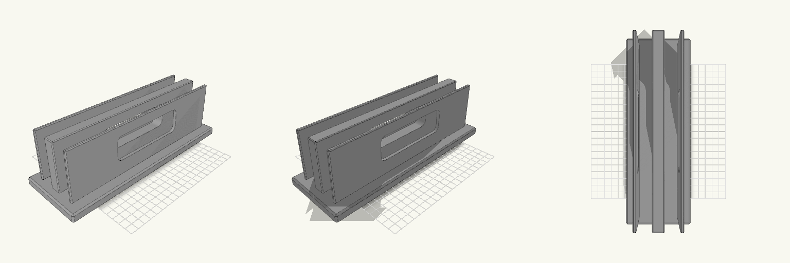
Dual Vertical Laptop Stand, 20mm Slots
A vertical stand that docks two closed laptops side by side on their edges, freeing up desk space. Built for a setup with a work laptop and a personal laptop sharing one desk. Each slot has a window cut through its walls, so a hand can rest on a lid to check for heat without removing the laptop. What it's for Holding two closed laptops upright, one per slot, with a solid 15 mm divider between them. Checking temperature by touch through the window in each slot wall. Staying put thanks to a wide, weighted base that resists tipping. Dimensions Slot width: 20 mm each Divider between slots: 15 mm Outer and divider wall thickness: 4 mm (the divider is the 15 mm gap) Overall width: about 93 mm Overall depth: 270 mm base, 250 mm walls Overall height: about 82 mm (12 mm base plus 70 mm walls) Windows: 110 mm long by 35 mm tall, with rounded ends, through each wall Weight pockets: four underneath, each 14 × 80 × 7 mm Print notes Print with the base flat on the bed. No supports are needed for the main body. The underside pockets open downward. Fill them with steel washers, shot or similar, then seal them with felt, a sticker or a thin plate. Use PETG or PLA with 3 or more perimeters for stiff walls. Remix ideas Change the slot width to fit thicker laptops or ones in sleeves. Add a third slot for a tablet. Add rubber feet or a felt pad under the base. Add a cable cutout in the base for charging leads.