TWS Clamshell Enclosure
Created 4 days ago
Description
A hardshell housing for True Wireless Stereo (TWS) electronics, featuring a robust clamshell design. The base is sized exactly to the requested 52 × 48 × 24 mm footprint, finished with heavy corner rounding for pocketability and a recessed alignment lip for a clean seal.
- 1.8mm Hinge Channel: Sized to accept standard 1.75mm filament as a press-fit hinge pin.
- USB-C Port: Centred rear cutout ready for charging board alignment.
- Print-ready Orientation: The lid and body are separated and sit flush on the build plate for support-free printing.
Images
More like this
Explore more in Desk & Tech →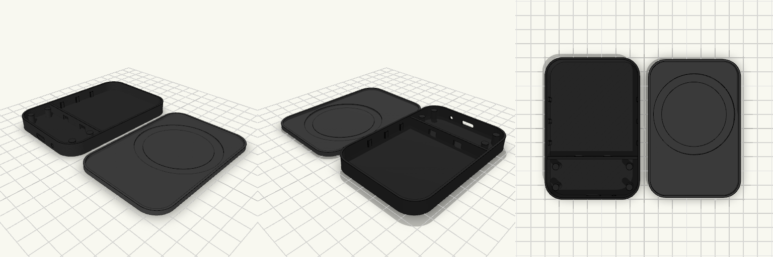
Wireless Battery Pack Enclosure
A rigid, minimalist two-part enclosure designed for a custom 5000mAh wireless power bank. The exterior mimics standard MagSafe packs with heavy corner radii and a flat profile, while the inside is sectioned to mount control hardware and charging coils safely. The base shell carries the primary mounting features: Battery Bay: Accommodates flat Li-Po cells with soft side-ribs to prevent lateral shifting without compressing the pack. PCB Mount: Four standoffs dimensioned for M2 self-tapping screws, separated from the battery bay by a low dividing wall with wire-routing channels. Ports: Cutouts on the bottom edge for a USB-C receptacle and a tactile switch. The top lid is hollowed to accept standard wireless charging hardware. Recesses for a 45mm Qi coil and a 56mm MagSafe magnetic ring are cut directly into the ceiling, leaving a minimal plastic floor (0.7mm to 1mm) to maximize magnetic adhesion and charging efficiency. A stepped lip aligns the lid securely into the base shell for final assembly.
27mm TWS Earbud Shell
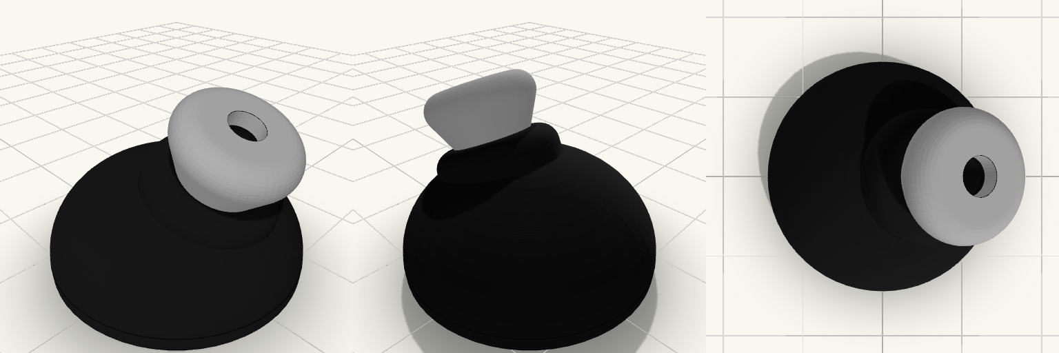
A True Wireless Stereo (TWS) earbud enclosure tailored for custom internals. The main exterior plate commands an exact 27 mm footprint, housing a domed chassis ergonomically tapered toward the ear canal. The structure includes exact hollows for: A Ø13 × 3 mm PCB A 401012 battery (4 × 10 × 12 mm) An 11.5 mm acoustic speaker The angled acoustic nozzle features a locking lip, allowing the included silicone ear tip to snap securely into place while remaining fully removable.
DataStack — Enclosure Core
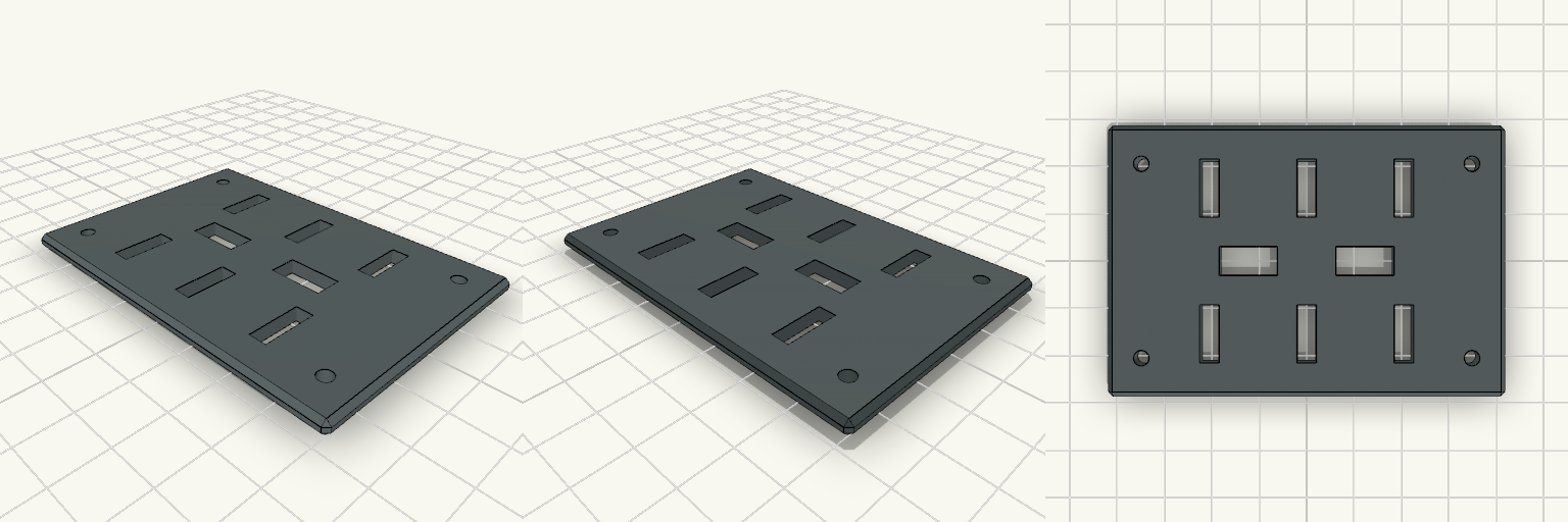
A lightweight, 4-bay enclosure body for 2.5" SATA HDDs. Features Stripped-down chassis with extensive material-saving cutouts Integrated rails for 4 drives Rear bosses for mounting a custom PCB backplane Designed to be printed on end (resting on the back faces) to avoid internal supports.
VL53L0X ToF Sensor Enclosure
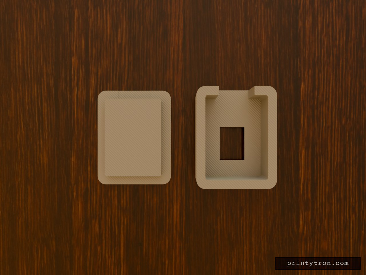
A compact, two-piece enclosure designed for standard VL53L0X Time-of-Flight breakout boards. It provides full protection for the PCB while maintaining a wide, unobstructed field of view for the optical sensor. What it's for Built to house a downward-facing ToF sensor. The flared aperture prevents the enclosure walls from clipping the sensor's ~25-degree conical field of view, while the flat backplate provides a clean surface for double-sided mounting tape. Dimensions Maximum Board Size: 14 mm × 19 mm (fits standard generic and Pololu breakouts) Internal Depth: 7 mm (plenty of room for direct-soldered wire joints) External Size: 18 mm × 23 mm × 9 mm (assembled) Sensor Aperture: 6 mm × 8 mm at the PCB, flaring out to 12 mm × 14 mm at the exterior Cable Routing: 8 mm wide exit slot on one end Print notes Print both parts flat on the build plate. The main body prints sensor-face down; the internal ceiling spans only 14 mm and will bridge cleanly on any well-calibrated machine without requiring supports. The lid includes a small clearance lip for a gentle friction fit.
Tiki Speaker Enclosure & Pedestal
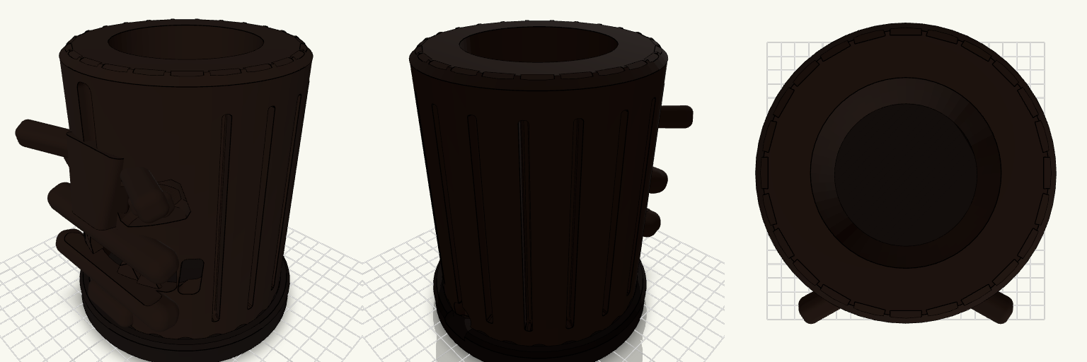
Sliding a hollow sleeve over a speaker means the device drags on the desk if you ever need to move it. This adds a dedicated pedestal base to the enclosure. The Tiki drops into a perfectly toleranced pocket, and the Echo Dot sits flat on the floor inside it, locking everything together as a single solid unit you can actually pick up. Dimensions Pedestal Footprint: 128 mm diameter Tiki Height: 140 mm (sits 10 mm deep in the base) Clearance: 0.75 mm gap around the lip so the shell drops in without binding Cable Management: Rear cutouts in both pieces align perfectly to let the power cord out
Horizontal LCD Control Enclosure
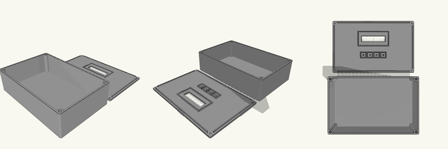
A horizontal electronic project enclosure designed for control panels and desktop instruments. The assembly features an internal mounting frame for a standard 1602 LCD module and four 12mm tactile push buttons. Components install from the underside of the top cover, ensuring that only the display area and button caps are visible from the exterior. The two-part construction secures together using four M3 screws with captured hex nuts embedded in the bottom housing. Overall dimensions: 220mm × 140mm × 60mm Hardware required: 4× M3 screws, 4× M3 hex nuts Component mounts: 1602 LCD PCB (80x36mm) and 4× 12mm tactile switches Print orientation: Both parts print flat on the build plate without supports