90 Degree Water Elbow, 5 mm Bore
Created today
Description
A set of four identical 90 degree elbow fittings for water lines, each with a 5 mm inside diameter and a 2 mm wall.
Each elbow has a smooth curved bend and two straight 14 mm legs. A small ridge at each leg end helps hold a tube in place.
- Inside diameter: 5 mm
- Outside diameter: 9 mm (2 mm wall)
- Leg length: 14 mm each
- Bend radius: 8 mm at the centreline
- Quantity: 4 identical elbows, spaced 25 mm apart
Images
More like this
Explore more in Home & Fixtures →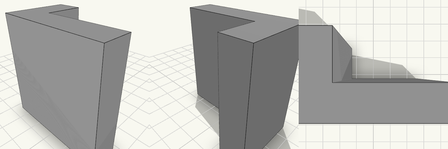
Anglewright — 90° L Profile
Anglewright is a clean 90° L profile with unequal legs: 2 in along one axis and 1.2 in along the other, standing 2 in tall. Both legs are 0.5 in thick, giving a simple right-angle section for corner bracing, spacing, or building up a frame. The form is a single continuous L, so the shape itself carries the function. Dimensions Overall height: 2 in (50.8 mm) Leg lengths: 2 in × 1.2 in (50.8 mm × 30.5 mm) Leg thickness: 0.5 in Corner angle: 90° Print notes At 2 in tall the profile sits comfortably within a typical print bed, so it can be printed standing up on its end with no special base. Lying on its side also works and keeps the flat L section stable on the plate. No supports are needed either way; the 0.5 in legs give plenty of contact area. Features Single-piece right-angle profile with no assembly Unequal legs for mixing offsets in two directions Small enough to print several at once for a set of matched braces
Garden-Plumbing Workhorse: BSP to 3/4 Hose Barb
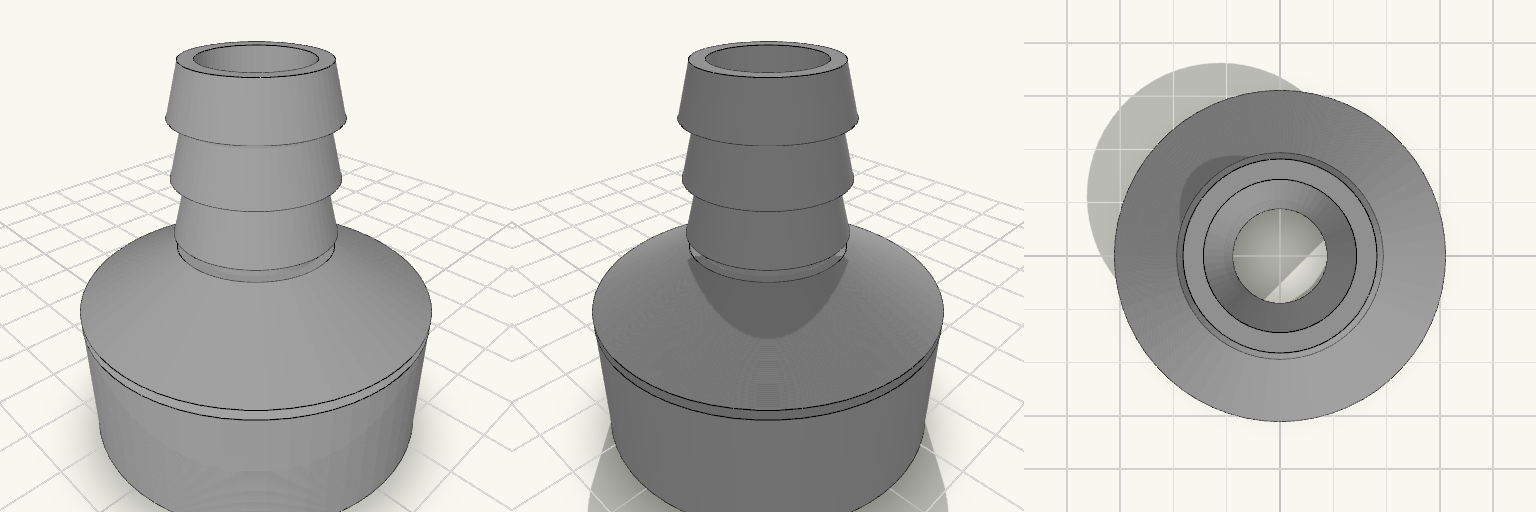
A straight-line adapter that bridges a 1-1/4" BSP female threaded socket to a 3/4" hose barb, with a tapered shoulder carrying the eye from the wide threaded end down to the narrow ridged nozzle. It reads like a piece of honest utility hardware: a ring of 11 TPI thread at one end, three crisp ridges at the other, and a 15 mm bore running clean through a compact 55 mm body — short enough to tuck into tight pump and tap arrangements without a loop of hose fighting for room. The barb's ridges ramp up gently from the tip and widen toward the body, then drop off in a sharp step — the hose slides on without a fight, and the step keeps it from backing off again. Design notes: 1-1/4" BSP female socket, 11 TPI, 41.91 mm major diameter, 18 mm deep Tapered transition from the socket down to the barb 19 mm barb with three retention ridges, 7 mm tall and spaced 8 mm apart, narrow at the tip and widening to a step at the body side, for 3/4" hose 15 mm bore through the full length; 55 mm overall Prints as a single piece, sitting upright at roughly 50 × 50 mm on the plate Fit and sealing: The thread is modelled at nominal size with no added clearance, so a first test fit against the male fitting is worth doing — if it binds, opening it out by 0.2–0.4 mm is the easy fix. For a watertight joint, wrap the thread with PTFE tape or seat a flat washer against the socket floor. The shortened barb leaves less hose length to grip; a hose clip just behind the final ridge makes up for it. Pairs naturally with garden hose, pump outlets and tank fittings.
100 mm OD Flange, 45 mm Bore
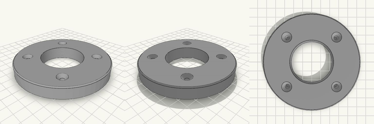
A flat round flange, 100 mm outside diameter and 13 mm thick, with a 45 mm bore straight through the middle. Four 5 mm holes sit on a 72 mm bolt circle at 45°, 135°, 225° and 315°, countersunk from the top face and 10.5 mm across at the rim. The outer edges carry a 1 mm chamfer, so there is no sharp rim to catch on. What it fits Bore: 45 mm nominal — measure the shaft, tube or spigot it goes over with calipers first. A printed 45 mm bore comes out undersized on most machines, so plan on reaming or drilling to size. Bolt pattern: four holes on a 72 mm bolt circle, at the diagonal positions rather than at 12/3/6/9 o'clock. Confirm the orientation of the mating part before drilling anything. Fasteners: 5 mm clearance with a countersink 10.5 mm across, sized around M5 flat-head screws so the heads sit at or just below the top face. Longer screws will not sit flush, and the 13 mm body sets how much thread you have to play with. Face: the 100 mm diameter leaves roughly 27.5 mm of material between the bore edge and the outer edge. What it does not have No hub and no raised face — it is a plain flat disc, so it will not self-centre on a register. No thread, no taper and no keyway in the bore. No O-ring groove or gasket recess; sealing has to come from the mating faces or a separate gasket. No second bolt pattern — if the part you are mating to has six or eight holes, or a circle other than 72 mm, this will not bolt on. Before you print Measure the bolt circle and the hole positions on the part you are mating to, centre-to-centre, and check that the four-hole diagonal layout matches. Also check that 13 mm of thickness clears whatever sits behind the flange, since the countersinks eat into the top face and leave less material under the heads than a plain 13 mm plate would suggest. Prints flat on the bottom face with no supports; the chamfer and the bore both come out clean laid down that way, and the countersinks form on the top surface without bridging.
10 mm Bore Screw-Together Coupler
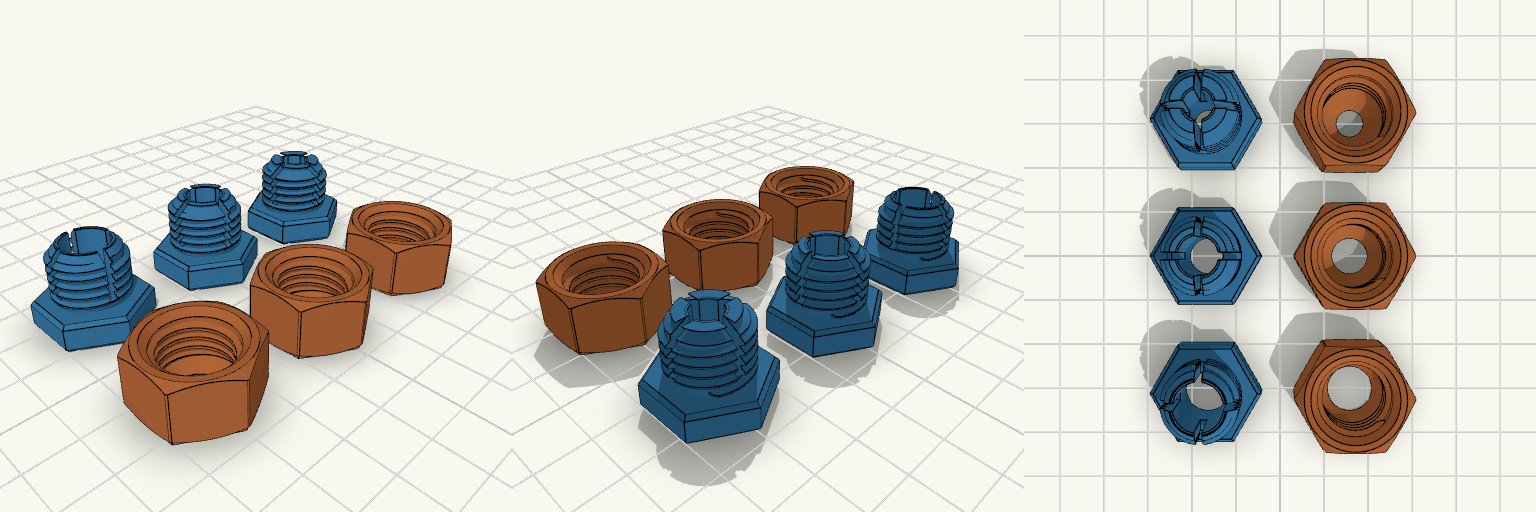
Złączka skręcana z zaciskiem, w trzech rozmiarach: na rurkę lub pręt 10 mm, 8 mm i 6 mm. Każdy zestaw to dwie drukowane części — część z gwintem zewnętrznym ma cztery szczeliny tworzące sprężyste palce, a nakrętka ma w dnie stożek. Dokręcanie nakrętki nasuwa stożek na skosy palców i zmniejsza otwór, więc złączka zaciska materiał zamiast tylko go przepuszczać. Korpus, sześciokąt i gwint 16×2 mm są takie same we wszystkich trzech rozmiarach. Zmienia się tylko otwór oraz stożek zacisku w nakrętce. Dopasowanie Host: zwykła okrągła rurka lub pręt o nominale 10, 8 albo 6 mm. Otwór w spoczynku: 10,5 mm / 8,5 mm / 6,5 mm. Gwint: 16 mm średnicy zewnętrznej, skok 2 mm; pasuje tylko do nakrętki z tego zestawu. Korpusy: sześciokątne, do klucza. Montaż: dwie drukowane części na rozmiar, skręcane razem. Zamienność: korpus i gwint są wspólne, ale stożek w nakrętce jest dobrany do rozmiaru — do prawidłowego zacisku używaj pary z tego samego zestawu. Sprawdź przed drukiem Zmierz rzeczywistą średnicę zewnętrzną rurki lub pręta. Materiał większy niż nominalny albo żebrowany nie wejdzie do otworu; materiał mniejszy może nie zostać zaciśnięty. Dokładna wartość zmniejszenia otworu podczas dokręcania nie jest sprawdzona w druku, więc przetestuj zacisk na złomowym materiale. Przy 6 mm palce zaciskowe są grubsze, więc zacisk jest sztywniejszy i może wymagać mocniejszego dokręcenia. Nie pasuje Gwint M10 ani pręt gwintowany; to otwór na gładki materiał, nie połączenie gwintowe. Standardowe gwinty rurowe metryczne lub BSP; gwint 16×2 mm jest specyficzny dla tej pary. Złączki do węża. Zastosowania ciśnieniowe; drukowany gwint nie tworzy uszczelnienia. Mieszanie rozmiarów: zestaw 10 mm nie jest do rurki 8 mm ani 6 mm, a zestawy 8 mm i 6 mm nie przyjmą rurki 10 mm.
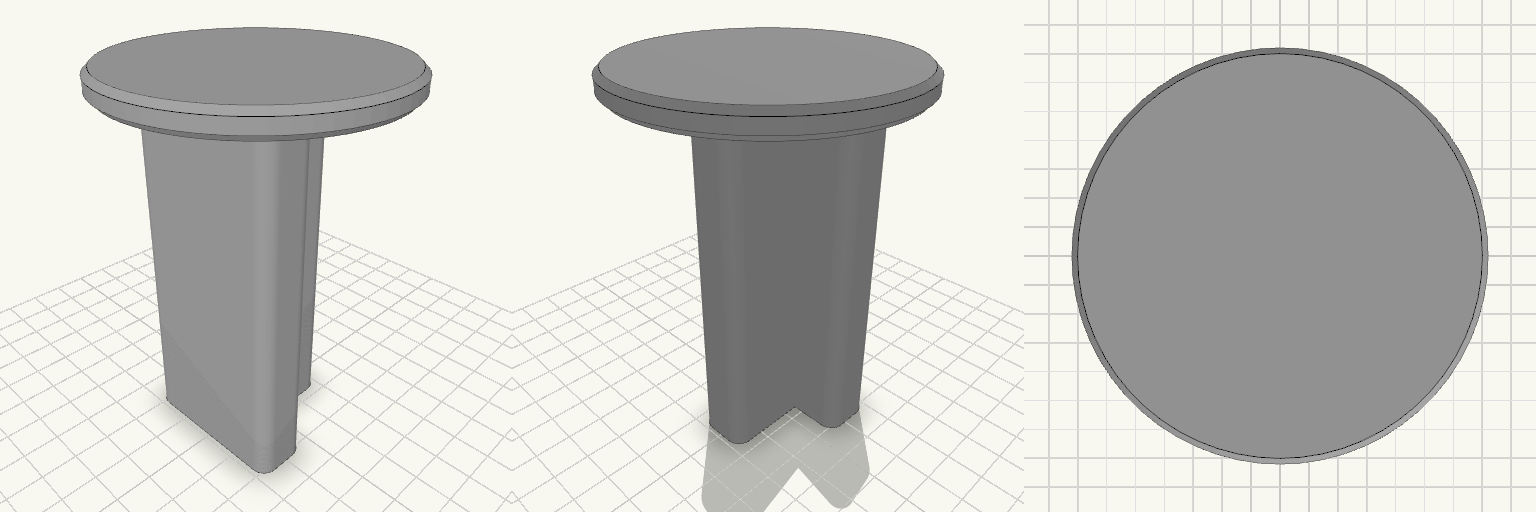
T-Post Cap With 3-Inch Round Platform
A slip-on cap for a steel T-post: 4 in tall, with a T-shaped socket that drops over the post and a 3 in round platform, 1/4 in thick, on top. Fits Steel T-posts, matched to the T-socket below. The socket is a T: a 36 mm crossbar, 7 mm wide at the stem entry, with a 7 × 30 mm stem running down, and a 4 mm wall following that T all the way around. Takes the place of a plain post cap and adds a flat, 3 in round surface on top of the post. Check before printing The socket is the whole fit, and its numbers are a starting size, not a standard — T-posts differ in flange width and web thickness between manufacturers and post weights. Measure the post you intend to use across the crossbar, across the stem, and across the full depth, then set the socket to those sizes plus a little clearance for paint and burrs before you commit filament. Nothing else on the part affects fitment. Does not fit Round posts, wooden 4x4 posts, or any post without a T cross-section. T-posts whose crossbar or stem is wider than the socket above — T-post profiles are not interchangeable, so do not assume a fit from the post name or the post weight alone. The cap prints as a single piece, 76 × 76 × 102 mm overall.
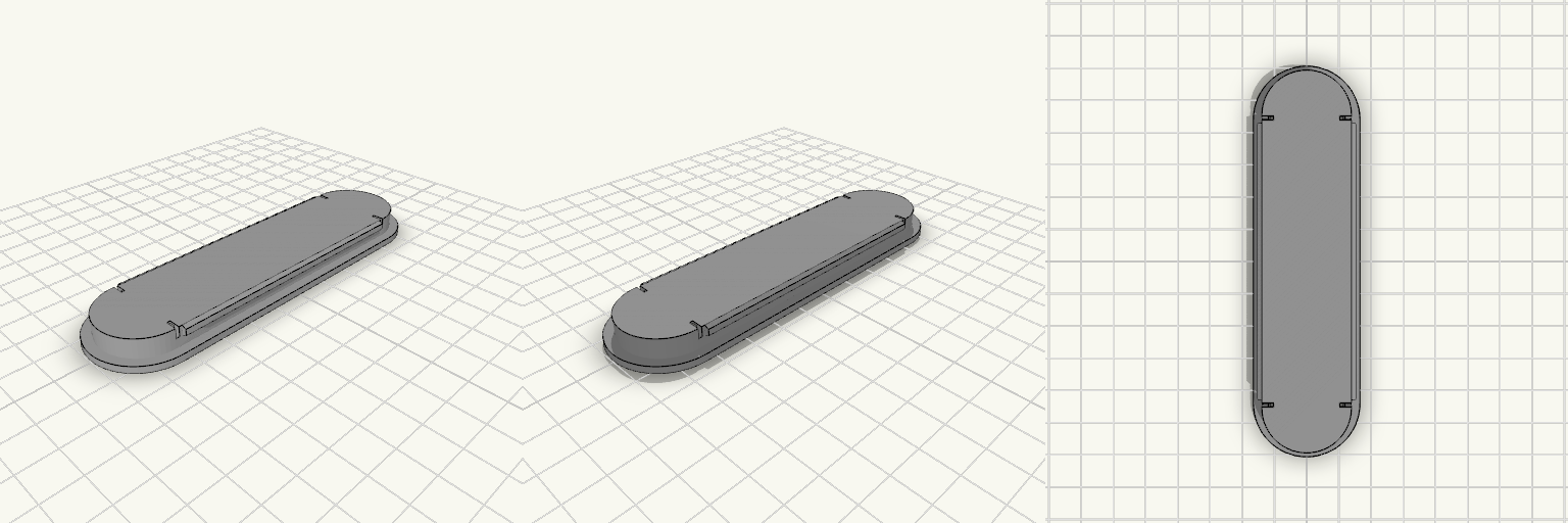
Tampão com travas para abertura semicircular
Um tampão para abertura de pontas em semicírculo resolve o encaixe torto: uma tampa reta entra forçada nas curvas e salta no primeiro esbarro. Esta peça assenta no vão por pressão, com duas travas flexíveis embutidas nos lados compridos, topo fechado por uma tampa fina e interior oco por baixo — cobre o buraco sem virar bloco maciço, e as paredes mais finas ajudam a peça a ceder no eixo X. Medidas que decidem o encaixe Abertura coberta: 27 × 114 mm, com pontas em semicírculo de raio 13,3 mm; o corpo tem 26,6 × 113,6 mm, já com a folga de encaixe. Aba de 2 mm em volta: assenta na borda e impede a peça de afundar no vão. Topo fechado por uma tampa de 0,5 mm, exceto nas fendas das travas, que chegam à face superior; parede de cerca de 1,8 mm em volta e interior oco por baixo. Duas travas embutidas nos lados compridos, com 84 mm de largura; as travas das pontas foram removidas para não brigar com a curva. As travas começam em 5 mm na altura e vão até 8 mm; o ressalto tem 3 mm de altura e as fendas sobem até o topo nesses pontos. Espessura total: 8 mm, contando a aba — o perfil fica baixo, rente à superfície. Peça completa: 32,6 × 119,6 × 8 mm. O contorno externo é contínuo; as fendas aparecem no topo apenas sobre as travas. Para imprimir Sai em uma peça só, sem montagem; nada de parafusos ou cola. A tampa de topo tem só 0,5 mm — fina para imprimir; reduza a velocidade nas últimas camadas para ela não ondular. As linguetas são curtas e finas: use um material que ceda um pouco — PETG funciona bem; PLA muito rígido pode rachar a trava no primeiro encaixe. Imprima com o lado da aba para baixo, apoiado na mesa, para as travas e as fendas ficarem limpas. Se o encaixe sair apertado ou folgado demais, ajuste a folga antes de mexer nas travas.