100 mm OD Flange, 45 mm Bore
Created today
Description
A flat round flange, 100 mm outside diameter and 13 mm thick, with a 45 mm bore straight through the middle. Four 5 mm holes sit on a 72 mm bolt circle at 45°, 135°, 225° and 315°, countersunk from the top face and 10.5 mm across at the rim. The outer edges carry a 1 mm chamfer, so there is no sharp rim to catch on.
What it fits
- Bore: 45 mm nominal — measure the shaft, tube or spigot it goes over with calipers first. A printed 45 mm bore comes out undersized on most machines, so plan on reaming or drilling to size.
- Bolt pattern: four holes on a 72 mm bolt circle, at the diagonal positions rather than at 12/3/6/9 o'clock. Confirm the orientation of the mating part before drilling anything.
- Fasteners: 5 mm clearance with a countersink 10.5 mm across, sized around M5 flat-head screws so the heads sit at or just below the top face. Longer screws will not sit flush, and the 13 mm body sets how much thread you have to play with.
- Face: the 100 mm diameter leaves roughly 27.5 mm of material between the bore edge and the outer edge.
What it does not have
- No hub and no raised face — it is a plain flat disc, so it will not self-centre on a register.
- No thread, no taper and no keyway in the bore.
- No O-ring groove or gasket recess; sealing has to come from the mating faces or a separate gasket.
- No second bolt pattern — if the part you are mating to has six or eight holes, or a circle other than 72 mm, this will not bolt on.
Before you print
Measure the bolt circle and the hole positions on the part you are mating to, centre-to-centre, and check that the four-hole diagonal layout matches. Also check that 13 mm of thickness clears whatever sits behind the flange, since the countersinks eat into the top face and leave less material under the heads than a plain 13 mm plate would suggest.
Prints flat on the bottom face with no supports; the chamfer and the bore both come out clean laid down that way, and the countersinks form on the top surface without bridging.
Images
More like this
Explore more in Home & Fixtures →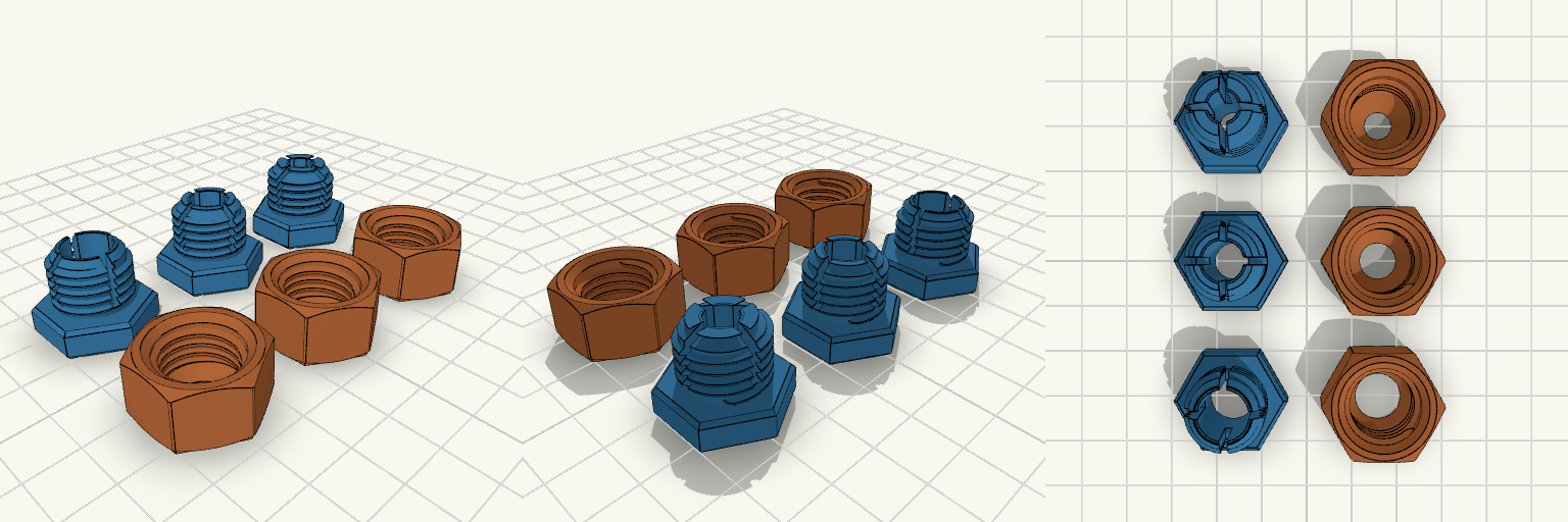
10 mm Bore Screw-Together Coupler
Złączka skręcana z zaciskiem, w trzech rozmiarach: na rurkę lub pręt 10 mm, 8 mm i 6 mm. Każdy zestaw to dwie drukowane części — część z gwintem zewnętrznym ma cztery szczeliny tworzące sprężyste palce, a nakrętka ma w dnie stożek. Dokręcanie nakrętki nasuwa stożek na skosy palców i zmniejsza otwór, więc złączka zaciska materiał zamiast tylko go przepuszczać. Korpus, sześciokąt i gwint 16×2 mm są takie same we wszystkich trzech rozmiarach. Zmienia się tylko otwór oraz stożek zacisku w nakrętce. Dopasowanie Host: zwykła okrągła rurka lub pręt o nominale 10, 8 albo 6 mm. Otwór w spoczynku: 10,5 mm / 8,5 mm / 6,5 mm. Gwint: 16 mm średnicy zewnętrznej, skok 2 mm; pasuje tylko do nakrętki z tego zestawu. Korpusy: sześciokątne, do klucza. Montaż: dwie drukowane części na rozmiar, skręcane razem. Zamienność: korpus i gwint są wspólne, ale stożek w nakrętce jest dobrany do rozmiaru — do prawidłowego zacisku używaj pary z tego samego zestawu. Sprawdź przed drukiem Zmierz rzeczywistą średnicę zewnętrzną rurki lub pręta. Materiał większy niż nominalny albo żebrowany nie wejdzie do otworu; materiał mniejszy może nie zostać zaciśnięty. Dokładna wartość zmniejszenia otworu podczas dokręcania nie jest sprawdzona w druku, więc przetestuj zacisk na złomowym materiale. Przy 6 mm palce zaciskowe są grubsze, więc zacisk jest sztywniejszy i może wymagać mocniejszego dokręcenia. Nie pasuje Gwint M10 ani pręt gwintowany; to otwór na gładki materiał, nie połączenie gwintowe. Standardowe gwinty rurowe metryczne lub BSP; gwint 16×2 mm jest specyficzny dla tej pary. Złączki do węża. Zastosowania ciśnieniowe; drukowany gwint nie tworzy uszczelnienia. Mieszanie rozmiarów: zestaw 10 mm nie jest do rurki 8 mm ani 6 mm, a zestawy 8 mm i 6 mm nie przyjmą rurki 10 mm.
114mm Square Gutter S-Bend Section
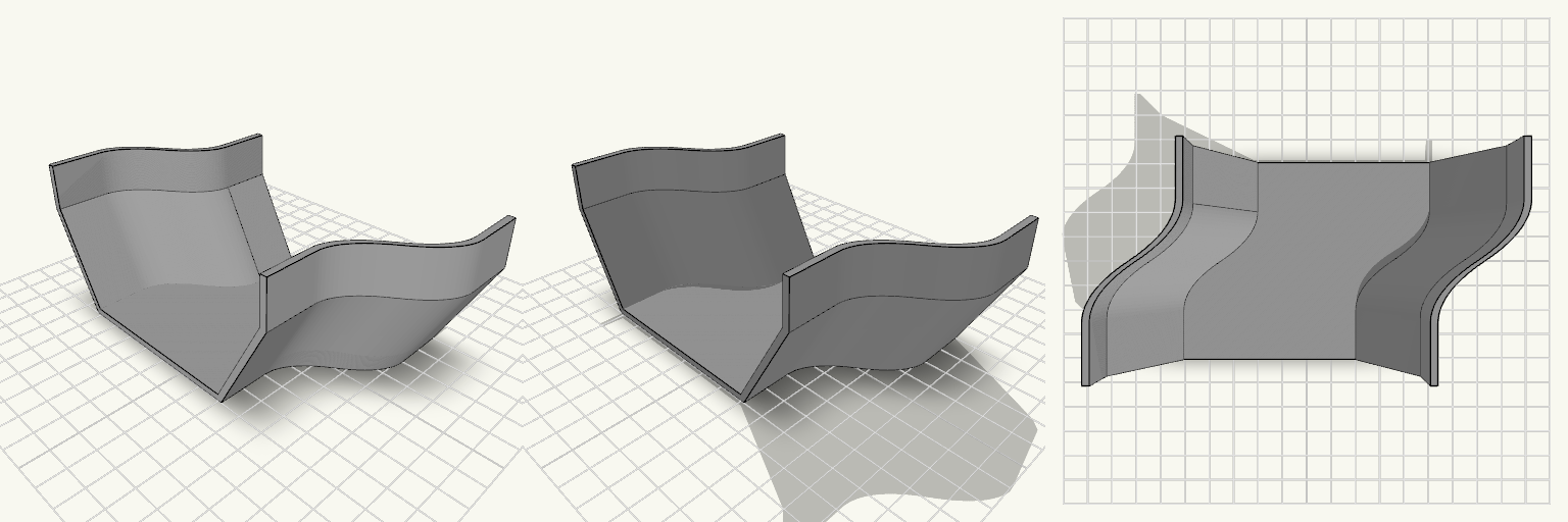
A square-profile gutter offcut with an S-bend that pulls the run 30 mm closer to the wall, replacing a straight section that sits too far out from the fascia. Overall width 114 mm, depth 57 mm, wall 2.4 mm Base flat 73 mm wide, vertical sides 18 mm tall, angled sections between Length 80 mm: 20 mm straight at each end, 40 mm S-bend between Offset 30 mm toward +X (wall side) Open-top hollow channel, end to end; print upright on the base, supports not needed
Four-Piece Baseboard Register Hood and Duct Kit
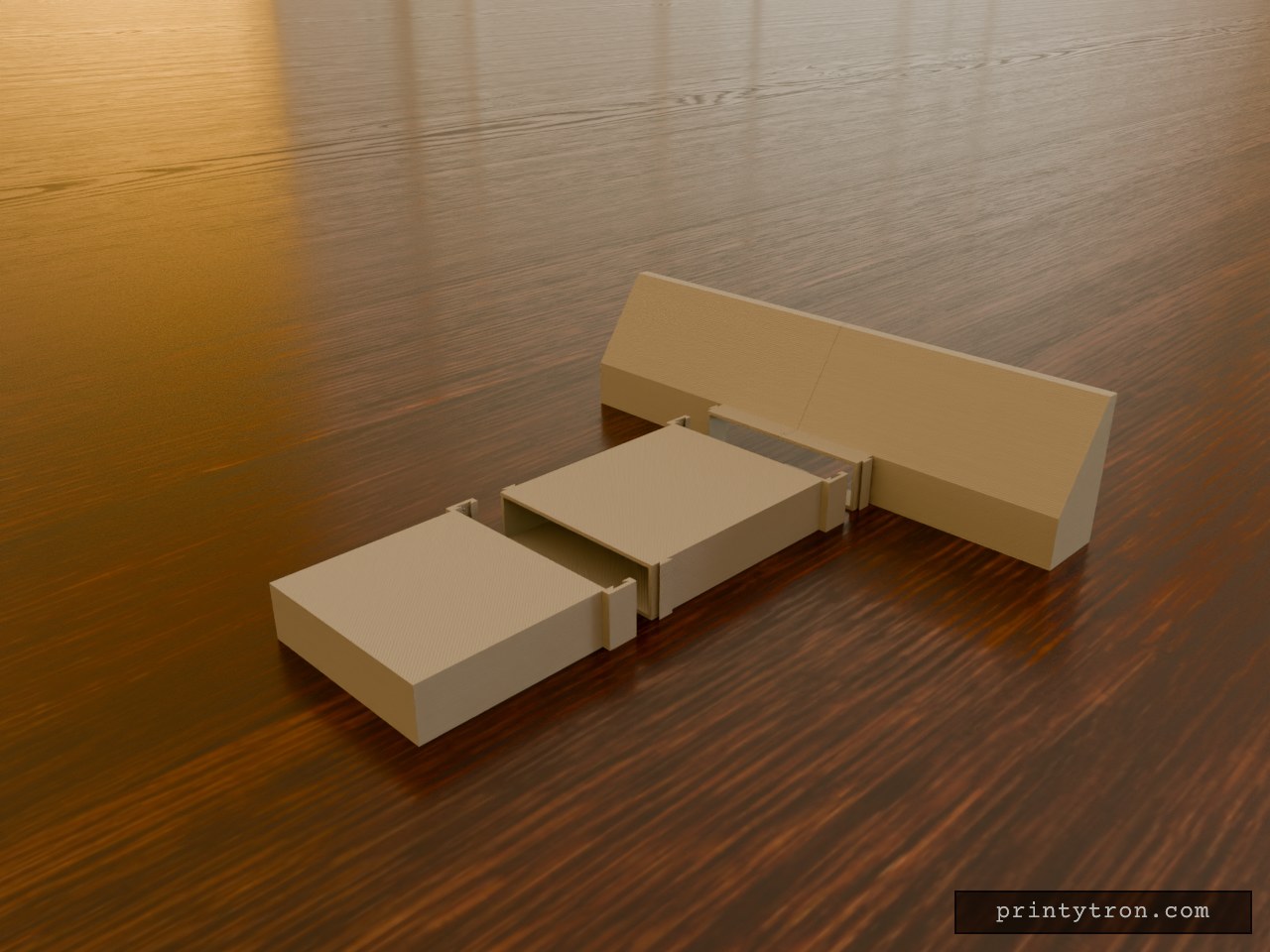
This is a four-part replacement hood and duct kit for a baseboard HVAC register: two hood halves, a straight extension tunnel, and a 90-degree side-turn end cap. When the hood halves are joined, the hood measures 450 mm wide along the wall, 80 mm deep, and 115 mm tall. The rear and bottom are open to take air from the baseboard void; the sloped front funnels that air into a centered horizontal nozzle at the lower front edge. The nozzle is 150 mm wide, 40 mm tall, and projects 20 mm forward. All four parts print separately and slide together with dovetail joints. The extension and cap sit on the plate beside the hood halves, not pre-assembled. The sliding joints use 0.3 mm clearance per side, and the chunk and cap sockets have small friction bumps. For an air-tight run, add foam gasket tape or silicone along the socket edges; test-print one joint before reducing clearance below 0.3 mm. Hood Specifications Printed hood halves: HoodLeft and HoodRight, joined by a central vertical sliding dovetail with 0.3 mm clearance. They slide together vertically along the seam. Shell: nominal 3 mm walls, with a 24 mm wide band across the center of the sloped roof and front wall thickened to 8 mm so the dovetail cuts through solid material. Joined hood footprint: 450 × 80 × 115 mm. Rear wall side and bottom floor are open. Outlet nozzle: 150 × 40 mm, projecting 20 mm forward. Nozzle side tracks: male dovetail on each outer side, 6 mm wide at the root and 12 mm at the tip, 3 mm deep, with 45° flanks. The wider printed hood half measures about 228 mm across, so check print-bed width. Extension Chunk Extension_Chunk is a straight hollow tunnel, 150 × 40 mm outside and 200 mm long, with 3 mm walls. Inlet socket: the first 20 mm has no top or bottom plate so it drops down over the nozzle; its side walls carry dovetail slots held 0.3 mm off the nozzle tracks. Small friction bumps sit at the top and bottom, two per side, to resist lifting off; they add friction rather than a positive click or seal. Outlet tracks: the same male dovetail as the hood nozzle, set 10 mm back from the end so the next chunk's socket fits over them. The socket end measures about 162.6 mm outside to house those slots. The tunnel has a bottom floor; it keeps the channel stiff and the sliding joints aligned over uneven flooring. Thinning that floor to 2 mm saves plastic; removing it will leak along the bottom. Chain as many chunks as the run needs; each one slides on vertically and can be swapped or added without tools. The chunk prints as a separate part alongside the hood halves, not pre-assembled. Side Turn Cap SideTurnCap is a 90-degree flat elbow end cap, nominal 150 mm wide, 40 mm tall, and 160 mm long, with 3 mm walls. Inlet: the same 20 mm dovetail socket as the chunk, open top and bottom, sliding vertically onto the chunk's outlet tracks with 0.3 mm clearance. Small friction bumps sit at the top and bottom, two per side, to resist lifting off; they add friction rather than a positive click or seal. Front end: closed off completely. Vent: one entire side wall is open as the exhaust; the top and bottom plates stay intact. Vanes: three internal quarter-circle turning vanes, 2 mm thick, with radii of 36, 72, and 108 mm, running the full interior height to turn airflow 90° out the side opening. The inlet gaps are an even 36 mm, including the gap to the far wall. Flip: the top and bottom are identical and symmetrical, so turning the cap upside down directs air out the other side. The socket end measures about 162.6 mm across; the cap prints as a separate part beyond the chunk on the plate.
Bug Zapper Battery Cover 27.65 x 60 mm
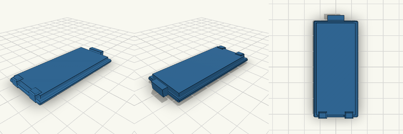
Sliding battery compartment cover plate for a bug zapper, 27.65 x 60 mm. A locating lip sits in the compartment opening, a latch tab sits at one end, and two low retention tabs at the opposite end keep the cover from falling out. Plate: 27.65 x 60 x 2 mm, chamfered edges Lip: 23.65 x 56 mm, 3.8 mm total height Retention tabs: two, 5 mm wide, flush with lip height, at X = ±8 mm Latch tab: 10 mm wide at the +Y end Grip grooves on the outer face Dimensions are estimates; verify against the original opening
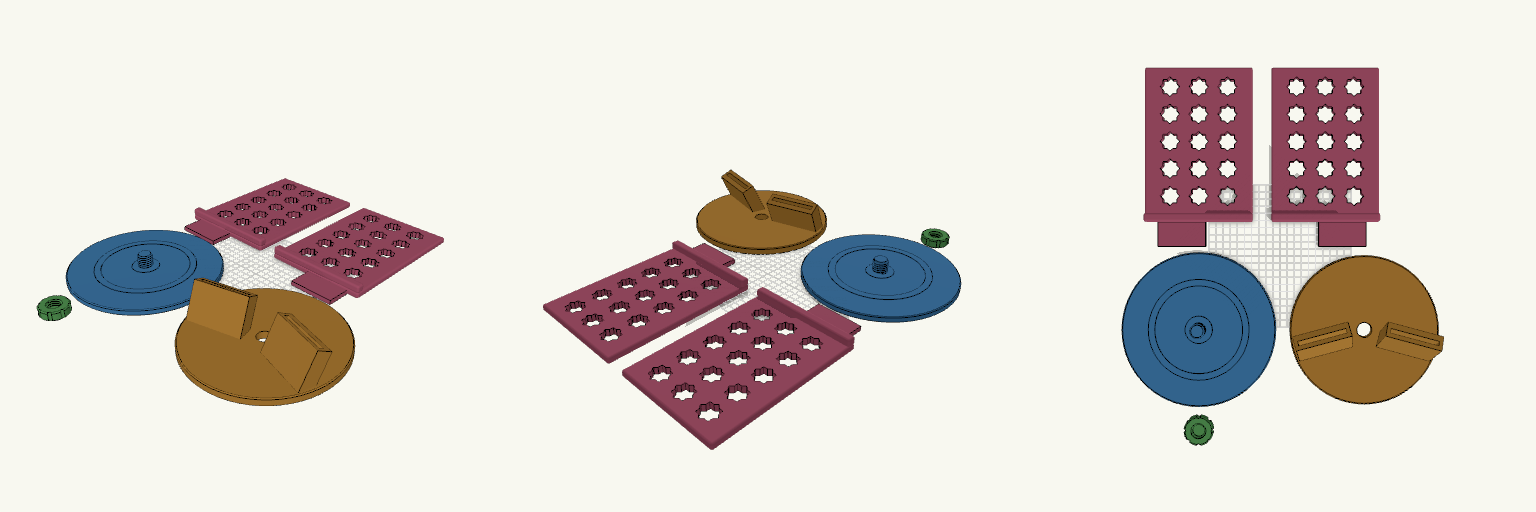
Swivel Quran Stand
A rehal-style book stand with a turntable base and two backward-leaning panels, pierced with eight-pointed khatam stars. The stars cut filament use while leaving a solid perimeter frame. A narrow gap between the panels takes the book's spine, and a rounded lip along the bottom edge holds the pages. Base: 214 mm disc with a coarse threaded pivot post and low bearing rings. Swivel carriage: spins 360° on the post. Two angled slot blocks are printed into it, with no supports needed. Retaining cap: screws onto the post to lock the carriage on, no metal or glue. Panels: two mirrored panels, 150 × 215 mm, with a flat tongue that slides into each carriage slot. Designed around a 170 × 240 mm book of about 1.5 kg, on a 220 mm bed with a 0.4 mm nozzle. Panels print flat on their backs. Flip the cap so its top is on the bed.
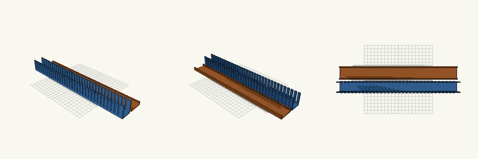
Finger Trunking with Snap-On Lid
Finger trunking that blocks access to your mounting holes is a problem. This one has floor slots cut where the screws and the access hole need to be, plus a snap-on lid. The walls are free-standing fingers with barbs at the tips. The lid's inward lip clips under the barbs. Size: 340 × 30 × 35 mm, with 2 mm walls and a 2 mm floor. Fingers: 4 mm gaps on a 10 mm pitch. M3 slots: Four slots, 3.4 mm wide and 5.4 mm long. They sit at 10, 100.75, 191.5 and 282.25 mm from the left end, 90.75 mm apart. Access hole: 7 mm diameter, 201.5 mm from the left end. Slot line: All slots sit 10.786 mm toward +Y from the centreline. Printing: The trunking is longer than most print beds. Print it diagonally or split it. The lid lip is a small overhang when printed flat.