64mm Straight Cylindrical Pipe
Made by TrustyMarten
Created 1 months ago
Description
A straight cylindrical pipe designed for flow or structural use, featuring a centered continuous bore.
- Inner Diameter: 60 mm
- Outer Diameter: 64 mm
- Wall Thickness: 2 mm
- Length: 60 mm
Prints vertically without supports.
Images
More like this
Explore more in Home & Fixtures →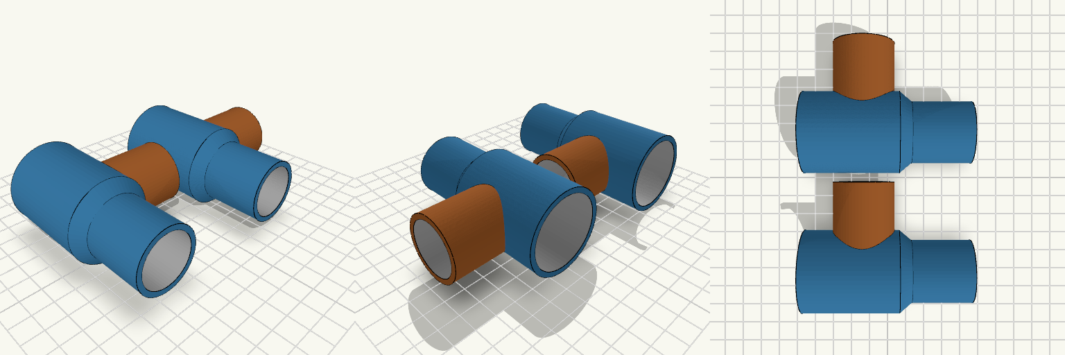
arbejde varme
This T pipe inlet joins a 31 mm line to a 41 mm line instead of stacking adapters that leak at every joint. The main run holds its 41 mm outside diameter all the way past the side branch, then necks down through a short taper to a 31 mm spigot long enough to grip a hose or slide into a coupling. The plate carries two identical copies side by side, 70 mm apart along Y, so one print gives you a pair; each copy is a separate hollow part with nothing to assemble. Fit and print notes Two identical pipes laid out side by side, 70 mm apart across Y Main run: 84 mm long overall per pipe — the 41 mm OD section carries on past the branch to within a few millimetres of its edge before reducing 41 mm centre section: 48 mm long Taper: 6 mm, from 41 mm OD down to 31 mm OD Reduced end: 30 mm of straight 31 mm OD spigot Other end: stays at the full 41 mm OD, no reduction Side branch: 31 mm OD, 45 mm out from the centreline Bores: 26 mm through the 31 mm spigot and the branch, 36 mm through the 41 mm section Wall thickness: 2.5 mm throughout Sits flat on the plate, no supports needed Only one end reduces, so orientation matters when you install it. The 84 mm length is what keeps the branch on the full-size section — check the gap before you commit, and dry-fit the 41 mm end first if it has to butt against something.
Curved Ø42 Pipe with Two Ø38 Branches
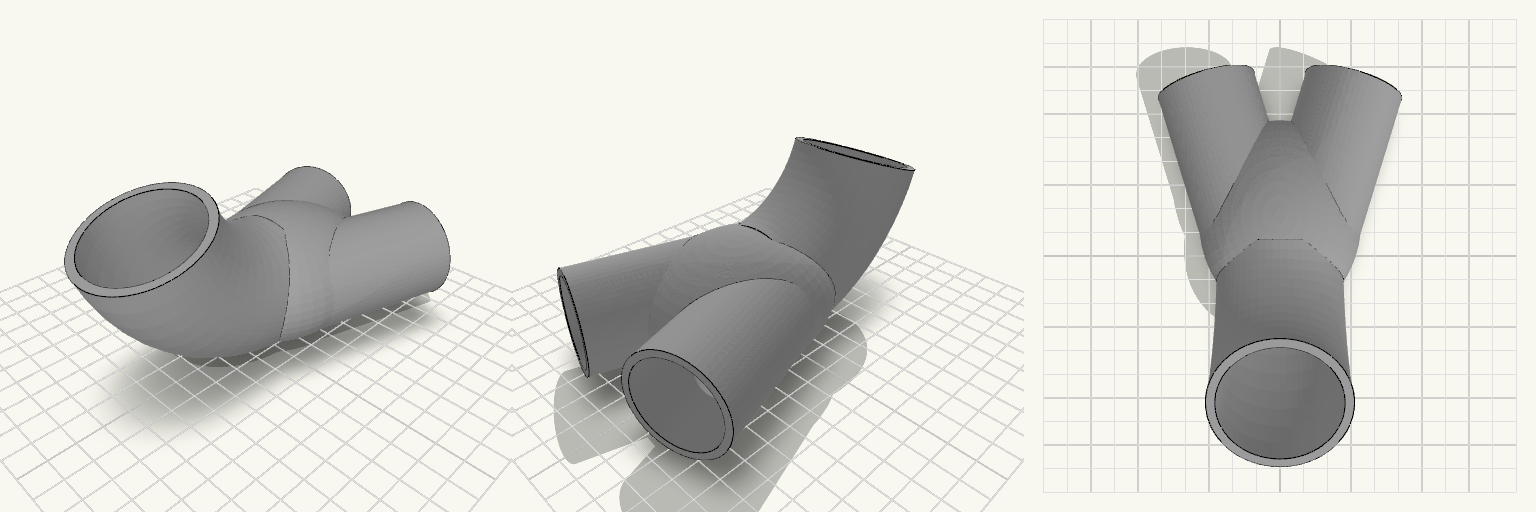
A hollow pipe that bends 70° along a 70 mm centreline and then splits into two diverging branches. The main bore is Ø42 with a 3 mm wall (Ø48 outside), giving a bend radius of roughly 57 mm. Where the bend meets the branches, the junction is stretched into a long egg-shaped blend — about 76 mm along the flow and 62 mm across — so the outside runs smoothly from the bend into each branch and the Ø42 bore narrows gradually into the two Ø33 bores, with no step or flat seam at the joint. On the print plate the two smaller branches lie flat and fan out sideways, side by side at ±17°, while the big curved pipe rises from them and bends upward, leaving its Ø42 inlet at the top of the bend rather than on the plate. The branches leave from either side of the junction rather than a single shared point, and the gap between them narrows quickly toward the blend, so only the outer stretch of each pipe stays clear for a hose — about 16 mm of clear space at the open ends, on centres roughly 56 mm apart. The whole part prints as a single hollow form with the branches already joined to the curve — no separate pieces or assembly. As it sits on the plate it measures about 92.6 × 141.2 mm with a height of about 69.9 mm, so check that against your bed before slicing. Keep the internal passages free of supports or bridging material so the flow stays unrestricted. Main bore: Ø42 inner, Ø48 outer, 3 mm wall Bend: 70° over a 70 mm centreline (≈57 mm radius), rising upward Branches: two, at ±17°, Ø38 outer, Ø33 inner (≈2.5 mm wall), 62 mm long, lying flat and fanning sideways Junction: stretched egg-shaped blend, approx. 76 mm along the flow and 62 mm across, feeding both branch bores without a step Branch spacing: ≈56 mm centre to centre, ≈16 mm clear at the open ends Footprint on the plate: approx. 92.6 × 141.2 mm, height approx. 69.9 mm Use it where a single round duct has to turn a corner and then divide into two angled outlets of a smaller diameter that each take a hose.
8.35 mm Fiberglass-Rod Joiner with Camera Arm
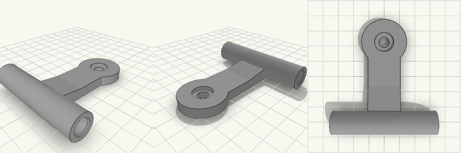
Replacement two-way joiner for the top-front-center of a fiberglass-rod printer enclosure. It splices two nominal 8.2 mm rods end-to-end and carries a flat-lying arm with a screw boss for a Sercomm RC8110 camera. Print it as one piece with the arm flat on the bed, then rotate the part about the rod axis during installation to aim the camera downward and toward the bed center. Specifications Rod sockets: 8.35 mm ID, 30 mm deep per side, 0.5 mm entry chamfers, separated by a 3 mm solid center stop; 63 mm overall sleeve length. Sleeve: approximately 14.35 mm OD with 3.0 mm wall thickness. Arm: 20 mm wide and 6 mm thick, extending 50 mm from the sleeve, with a root block and gusset blending it into the sleeve. Camera boss: 28 mm diameter and 6 mm thick, with a 6.6 mm through-hole and a 12 mm × 2 mm counterbore for a 1/4"-20 camera screw. Print footprint: 63 × 71.2 × 14.4 mm as oriented on the plate; the teardrop socket bores and flat arm are intended to print without support. Fit: press-fit for measured 8.19–8.20 mm rods; PETG wall thickness is sized to resist splitting and bending from the tensioned enclosure fabric.
LED Strip Corner Routing Bracket
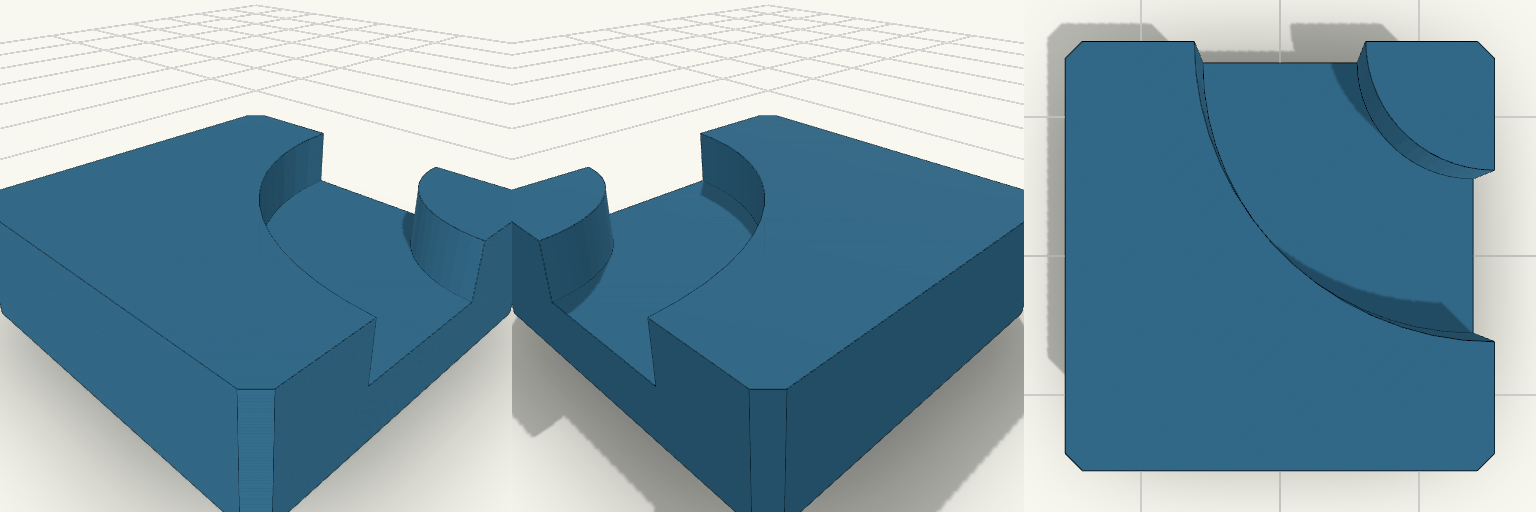
A 25 mm square corner block, 8 mm tall, with a quarter-circle channel on top that seats a 10 mm LED strip and turns it 90 degrees. Made for under-shelf lighting where the strip needs to follow an inside corner without kinking. The underside is flat, so it takes adhesive tape or double-sided foam. The channel is 10 mm wide and 4 mm deep, with a 12.5 mm centerline radius. It enters and exits through the two sides that meet at the far corner. Vertical corners carry a 1 mm chamfer. Remix hooks Block size (25 mm): the main lever. A 35 mm block with a 17.5 mm centerline radius gives a gentler bend for stiffer strips. Centerline radius (12.5 mm): keep it at half the block size so the channel meets the edges, or shrink it for a tighter turn. Channel width (10 mm): add 0.3 to 0.5 mm of clearance for strips with thick silicone sleeves, or narrow it for bare strips. Channel depth (4 mm): deepen it to sink the strip below the surface, or make it shallower and add a diffuser lip. Height (8 mm): can be lowered to about 6 mm and still keep the 4 mm channel with a solid floor. Pairs with Straight strip sections between corners, with one bracket per inside corner. A snap-in diffuser cover cut to the same 10 mm channel width. A mirrored variant for the opposite corner direction. Print notes Print flat on the back, with no supports needed. Use PETG or ABS if the bracket sits near warm drivers.
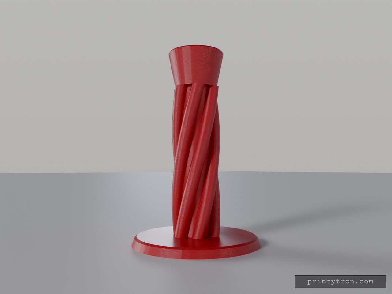
Twisted Column E27 Lamp Stand
A table lamp stand with a twisted six-lobe column rising from a round base to a cup that holds a standard E27 lamp socket. A 12 mm bore runs down the centre and a 7 mm channel carries the cable out the back of the base, so the wiring stays hidden. Remix hooks Socket pocket: 40.6 mm diameter, 26 mm deep. Measure your socket body and adjust socket_d before printing; many holders vary by a millimetre or two. Twist and lobes: 120° twist, 6 lobes. Change the twist angle for a gentler or more dramatic spiral, or the lobe count for a different silhouette. Height: the column is 140 mm; total height is about 182 mm. Taller columns suit larger shades. Base: 120 mm diameter, 8 mm thick. Widen it or add weight (coins, steel washers) for large shades. Set-screw hole: a 3.2 mm cross hole near the cup top is there for an M3 grub screw to lock the socket. Pairs with: an E27 socket with threaded nipple or clip-in body, a fabric cord with inline switch, and any E27 drum or cone shade. Print upright without supports. Use mains-rated, certified electrical parts, and a low-heat LED bulb rather than incandescent.
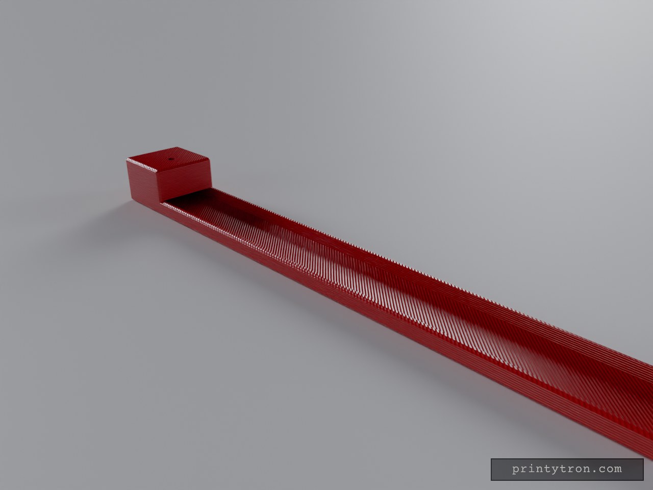
Long Ash-Catching Incense Holder
A 250 × 30 mm incense holder with a shallow trough running its full length, so ash from a burning stick lands in the channel and stays off the shelf. A raised block at one end carries a 3 mm stick hole angled 35° out over the trough. The channel continues underneath the block, so ash drops straight into it. Remix hooks Stick hole diameter (3 mm): The default is snug for thin sticks. Open it to 3.3–3.6 mm for thicker ones, or to about 2.5 mm for fine sticks. Hole angle (35°): A steeper angle makes the stick stand more upright and shortens the ash path. A shallower one lengthens the burn path and needs a longer tray. Trough depth (5 mm) and floor (2 mm): Deepen the trough for loose ash or to hold a layer of sand. The side walls are 2 mm, so widening the trough thins them. Overall length (250 mm): This is a free choice. Shorten it for shorter sticks. The block is 30 mm long and 22 mm tall. Block height (22 mm): Raise it to let longer sticks clear the tray end. Pairs with A thin layer of sand or ash in the trough to catch embers. Multiple holes along the block for several sticks. A lid or cover cut from a flat strip for storage. Print flat with the base down. The angled hole is drilled through the block, so check how your slicer handles the overhang at the angle and consider supports if it sags.