70×45×10.25 mm Sliding-Lid Enclosure with USB-C Cutouts
Created today
Description
What it's for
A sleek-modern two-part enclosure for a small electronics board. The body has two USB-C openings on one short end so the ports can be reached with the lid in place. The lid slides into grooves along the long walls and is stopped by the closed end; three grip ridges at the pull end help you slide it open. Four corner bosses inside give a PCB something to screw down to, and no screws are needed to close the lid. The body and lid print as two separate pieces.
Dimensions
- Body: 70 × 45 × 10.3 mm as laid out; 1 mm walls; vertical corners rounded at 2 mm; top and bottom edges square.
- Lid: 68.7 × 41.8 × 1.5 mm, with 0.2 mm clearance in the side grooves and three shallow grip ridges.
- Assembled height: 10.25 mm.
- USB-C cutouts: two rounded 9 × 3.2 mm plain slots on the short end, with a 3 mm gap between them (centres 12 mm apart, ±6 mm from the middle); the slots sit 2.8 mm above the inside floor.
- Screw bosses: four at the corners, 6 mm across with 2.6 mm holes for M3 self-tapping screws, 4.75 mm tall and stopping 3 mm below the rim.
Compatibility
Designed around an ESP32-S3 N16R8 board, but the corner bosses use a generic 6 mm / 2.6 mm layout and may not match that board's mounting holes. The USB-C slots sit low, while the bosses hold a board above the floor, so the slots line up only with a board resting directly on the floor. Check the board's hole spacing and port height before printing.
Print notes
Print the body with the open side facing up so the bosses and inner groove come out clean. Print the lid flat beside the body. Because the sliding fit is not verified in practice, print the lid first and check it in the grooves before committing to the body.
Remix ideas
- Fit the boss positions and USB slot height to an exact ESP32-S3 N16R8 board layout.
- Add screw holes or a latch if the lid should be held more securely than by sliding friction.
- Resize the boss holes for M2.5 screws or heat-set inserts.
- Move or widen the cutouts for a different connector layout, or add a third opening on another face.
- Cut a vent grille into the lid for boards that run warm.
Images
More like this
Explore more in Desk & Tech →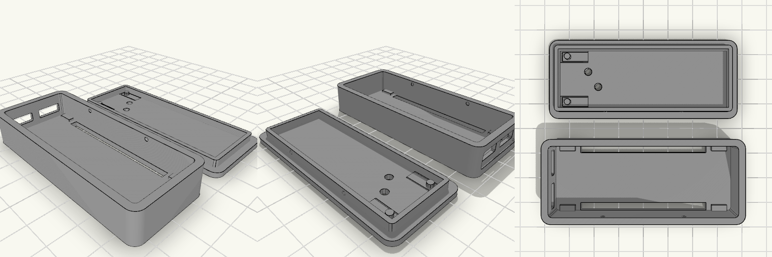
Sleek Ball-Bump ESP32-S3-N16R8 Enclosure v 3
A sleek, modern shell for the ESP32-S3-N16R8 dev board, built around a snap-fit lid instead of screws or hooks. Rounded vertical corners and 2.5 mm walls give it a clean, finished look, while the lid's four ball bumps click into shallow dimples in the long walls: self-centering, no visible hardware, and no layer-line hooks to snap off. A shared counterbore around the USB-C ports lets bulky cable overmolds seat flush against the wall, so the board sits low and the cable still plugs in fully. The lid now carries two cantilever button tongues, and the body is opened underneath for pins from below. Design notes Board fit: internal cavity of 69.8 × 26.2 × 10.25 mm, with about 0.4 mm clearance per side on a 69 × 25.5 mm board. The long rails are now short pads at each end, and overall height is about 12.3 mm. USB-C access: two 9.8 × 3.8 mm cutouts with 0.5 mm rounded corners, separated by a 3 mm strut on the short wall. A single 25.6 × 7 mm counterbore, 1.2 mm deep, wraps both openings so overmolded plugs clear; the strut stays at full depth behind it to keep the board edge captive. Lid and buttons: 2 mm plate with an inner lip; four 0.8 mm ball bumps engage shallow dimples with about 0.5 mm engagement and 0.3 mm interference. Each cantilever button is a tongue cut free of the lid plate by a U-shaped slot, thinned to 0.7 mm, with a 2.4 mm nub under the free end to press the board button. The old plain button holes are gone; the two 3 mm LED holes remain. Button positions are estimated rather than measured, so check them against your board variant before printing. Bottom pin access: two 50 × 3 mm slots run through the floor under the header rows, 22.86 mm apart, so pins can pass through from the bottom. Printing: the shell and lid are separate pieces, sized for PETG. They are laid out side by side on the plate, not stacked, within about 74.8 × 70.4 × 12.3 mm.
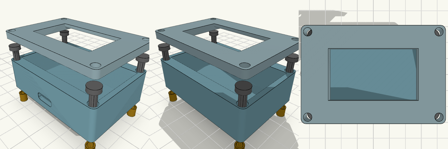
ESP32 Enclosure with 1.3 Inch OLED Lid
Two-piece enclosure for a 30-pin ESP32-WROOM-32 DevKit V1 with a 1.3 inch SH1106 OLED mounted in the lid. Shown exploded with heat inserts and M3 screws aligned to the corner holes. The lid has a 35.5 x 34.5 mm recess on the underside that holds the OLED PCB, and a 35.5 x 20.5 mm window through the front panel for the visible display area. ESP32 pocket: 52 x 28 mm, 14 mm deep Outer size: about 56.8 x 40.4 mm, 2.4 mm walls Front USB-C slot, 10 x 4 mm Four corner screw holes for M3 screws and heat inserts Front panel thickness behind the window: 1.6 mm Print the lid face-down for a clean front surface.
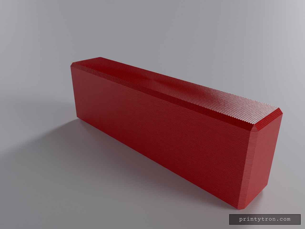
Desk Holder for 6 USB Sticks
A solid block with six angled slots that keeps USB-A sticks upright on the desk instead of loose in drawers. Each slot leans back 30 degrees, so labels on the sticks face a person seated at the desk. Each slot is sized for a standard USB-A stick with a little room to spare, and the slots are separated by 2.5 mm dividers. The outer edges have a small chamfer, and the base sits flat on the bed with no supports needed. Capacity: 6 USB-A sticks Slot size: 13 mm wide, 6 mm deep Slot angle: 30 degrees tilted back Divider thickness: 2.5 mm Overall size: about 95 mm long, 19 mm deep, 30 mm tall Print orientation: flat on its base, no supports
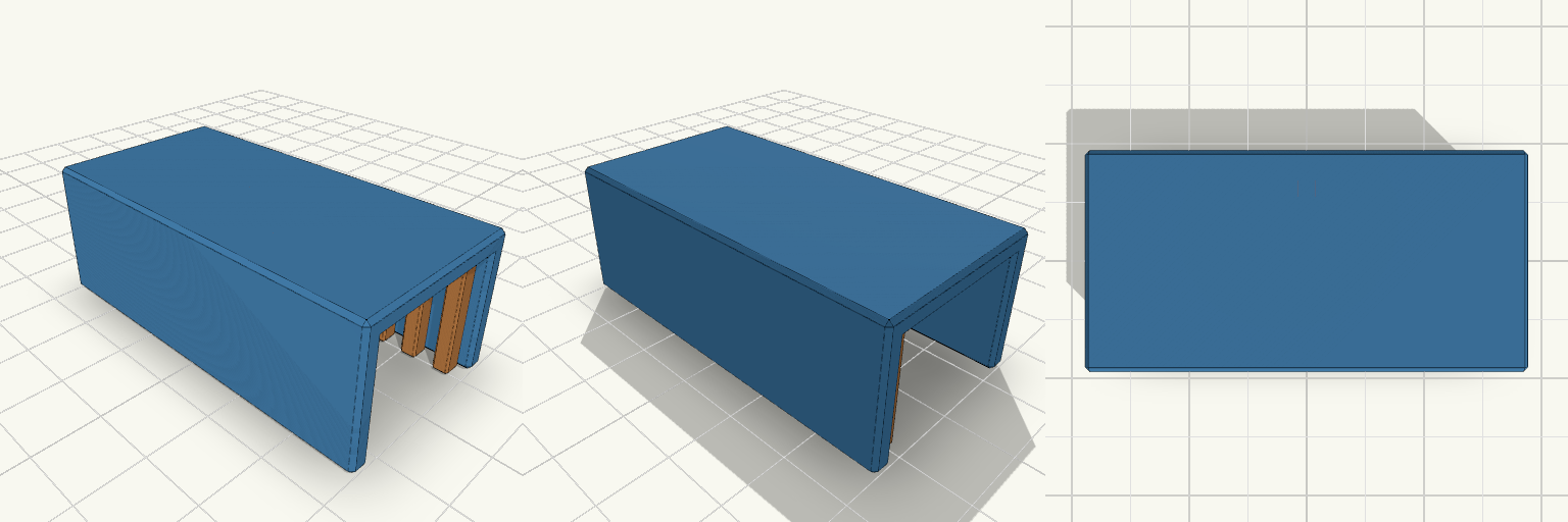
90mm USB Fan Guard Cloth Comb Clip
A cloth-hanging clip for the wire guard of a small USB desk fan, roughly 90 mm across. It holds a damp cloth in front of the grille so the airflow picks up moisture and cools a little as it passes, a basic evaporative cooler for a desk. What it fits Small USB fans with a wire or rim guard around 90 mm across. Damp cloths, such as a thin cotton towel or tea towel, pinched along one edge. What it does Rear arm at Y=0 sits on the guard side. A 30 mm deep spine runs across the top. Front arm at Y=27–30 hangs the cloth side. Eleven thin fingers, 2.4 mm wide and pitched at 5.4 mm, pinch the cloth edge so it hangs flat instead of bunching. Overall size: 60 mm wide, 30 mm deep, 22 mm tall. Check before printing Guard wire or rim thickness. No slot is sized to a specific wire yet. Measure the guard wire or rim and adjust the gap before relying on the grip. Cloth standoff. The cloth sits about 27 mm from the guard-side arm, not the 15 mm originally targeted. Shorten the spine if the cloth needs to sit closer. Known incompatibilities Not intended for fans with a solid or thick moulded frame in place of a wire guard. Not tested against any particular fan model. Verify the guard dimensions first. Keep the cloth damp, not dripping, and keep water and wet cloth away from USB connections and the fan's electronics.
Platinenabdeckung 20x20 mm mit Öse
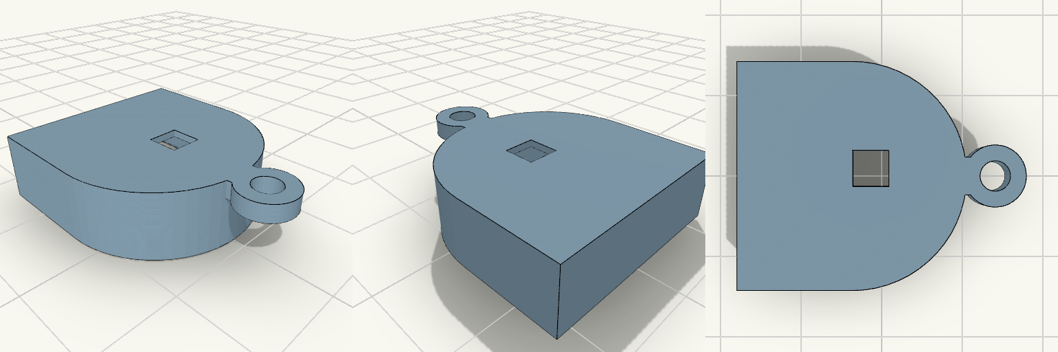
Abdeckung für eine 20×20×4 mm große D-förmige Platine mit Einrastnasen, Tasteröffnung und Schnuröse an der Rundung. Gesamthöhe 7,8 mm, Decke 0,8 mm, Wandstärke 1,8 mm Tasteröffnung 3,8 × 3,8 mm Öse: 6,5 mm Außendurchmesser, 3,2 mm Bohrung, 2 mm dick, bündig mit der Oberseite Öse sitzt mittig an der Rundung (Y = 0) auf der +X-Seite Empfohlen: transparentes PETG oder PLA
SPET Driver Module
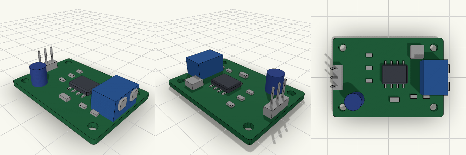
A postage-stamp-sized green driver board in the spirit of a classic hobby breakout module. It stands in for a smart tap's SPET driver stage: a 35 × 25 mm PCB carrying a placeholder driver IC, a few passives, a capacitor, an inductor, and an LED. The exact circuit is deliberately left generic. Supply: 5 V DC via a 3-pin 2.54 mm input header (5V, GND, signal) on the left edge. Output: 2-position terminal block on the right edge. Mounting: four 2.5 mm holes, 3 mm in from each corner. Height: tallest part is the terminal block, about 7.6 mm above the board base. Remix hooks: the parameters at the top of the file and each component module can be swapped for the real parts.