SPET Driver Module
Created today
Description
A postage-stamp-sized green driver board in the spirit of a classic hobby breakout module. It stands in for a smart tap's SPET driver stage: a 35 × 25 mm PCB carrying a placeholder driver IC, a few passives, a capacitor, an inductor, and an LED. The exact circuit is deliberately left generic.
- Supply: 5 V DC via a 3-pin 2.54 mm input header (5V, GND, signal) on the left edge.
- Output: 2-position terminal block on the right edge.
- Mounting: four 2.5 mm holes, 3 mm in from each corner.
- Height: tallest part is the terminal block, about 7.6 mm above the board base.
- Remix hooks: the parameters at the top of the file and each component module can be swapped for the real parts.
Images
More like this
Explore more in Desk & Tech →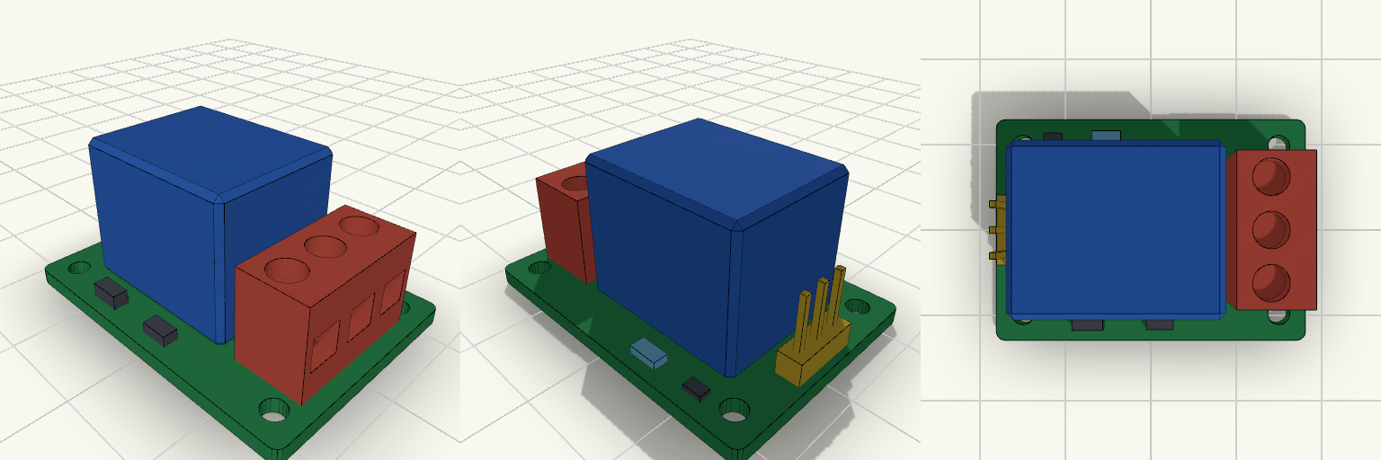
5V Single-Channel Relay Module
A 35 × 25 × 1.6 mm single-channel 5 V relay module for switching a solenoid valve from a compatible control circuit. It carries a blue 19 × 15.5 × 15.5 mm relay housing, a 3-pin control header, a 3-position screw terminal block for the switched load, an indicator LED and basic switching parts, with four 2.5 mm mounting holes. Remix hooks Board size: pcbl and pcbw (35 × 25). Going to 50 × 26 gives a conventional layout with more room around the relay. Relay body: relayl, relayw, relayh (19 × 15.5 × 15.5) and relayx/relay_y. Swap in the dimensions of the real part. Connector positions: hdrx, hdrpitch, hdrn for the control header (VCC, GND, IN, 2.54 mm pitch); termx, termpitch, termn for the load terminals (COM, NO, NC, 5.08 mm pitch). Mounting holes: holed (2.5) and holeinset (3). Colour coding: yellow header is low-voltage control, red terminals are the switched load. Keep them visually distinct in any variant. Pairs with: an enclosure with roughly 17.5 mm of clearance above the board, standoffs on the four holes, and a flyback-protected solenoid valve. The LED, transistor, diode and resistor are placeholders for layout, not a specific circuit.
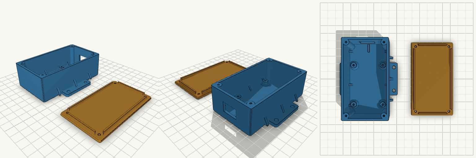
マイコンケース
A two-part enclosure for a 47 × 57 mm STM32F103 board, with a screw-down lid, external mounting flanges and a cable opening at the connector end. The base has 2.5 mm walls, four board bosses at 37 × 50 mm spacing holding the board 5 mm above the floor, and four corner posts for the lid screws. The lid has a locating lip and four clearance holes. Triangular gussets reinforce the flange-to-wall joints and the wall-to-floor joints, and the internal corners are rounded. Total height with lid: 35 mm Connector end extended 20 mm (+Y), with an adjustable cable opening Lid screws: M2.5 self-tapping, 2.2 mm pilot holes in the corner posts Adjustable: hole spacing and offset, boss height and hole size, flange hole size and positions, cable opening, extensions Board hole spacing is approximate and should be checked against the real board
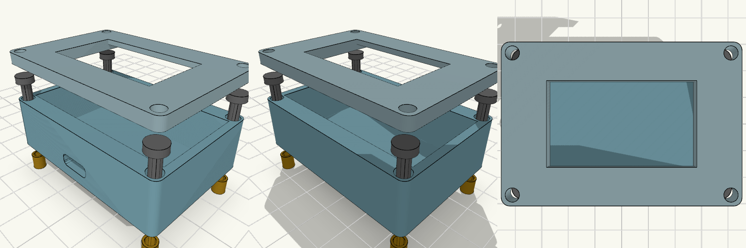
ESP32 Enclosure with 1.3 Inch OLED Lid
Two-piece enclosure for a 30-pin ESP32-WROOM-32 DevKit V1 with a 1.3 inch SH1106 OLED mounted in the lid. Shown exploded with heat inserts and M3 screws aligned to the corner holes. The lid has a 35.5 x 34.5 mm recess on the underside that holds the OLED PCB, and a 35.5 x 20.5 mm window through the front panel for the visible display area. ESP32 pocket: 52 x 28 mm, 14 mm deep Outer size: about 56.8 x 40.4 mm, 2.4 mm walls Front USB-C slot, 10 x 4 mm Four corner screw holes for M3 screws and heat inserts Front panel thickness behind the window: 1.6 mm Print the lid face-down for a clean front surface.
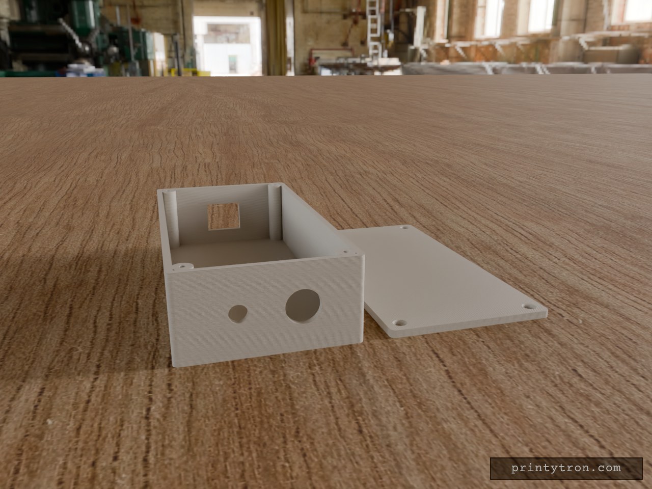
Bulkhead Signal Box with RJ45 and SMA
A compact 130 × 65 × 35 mm enclosure in the spirit of a field-radio interface box: Ethernet in one end, antenna and cable gland out the other. The lid sits flush and is held by four M2.5 × 10 mm countersunk screws threading into corner posts. RJ45 end: 16.5 × 14 mm rectangular opening, centred in width and height. Other end: 6.5 mm hole for a through-mount SMA connector and a 12.5 mm hole for a PG7-style cable gland, spaced evenly across the 65 mm width and centred in height. Walls: 2.5 mm; lid 3 mm, printed flat beside the box. Screws: 2.1 mm pilot holes in the posts for self-tapping M2.5; countersunk clearance holes in the lid.
Cyclops Visor Smart Goggles Chassis
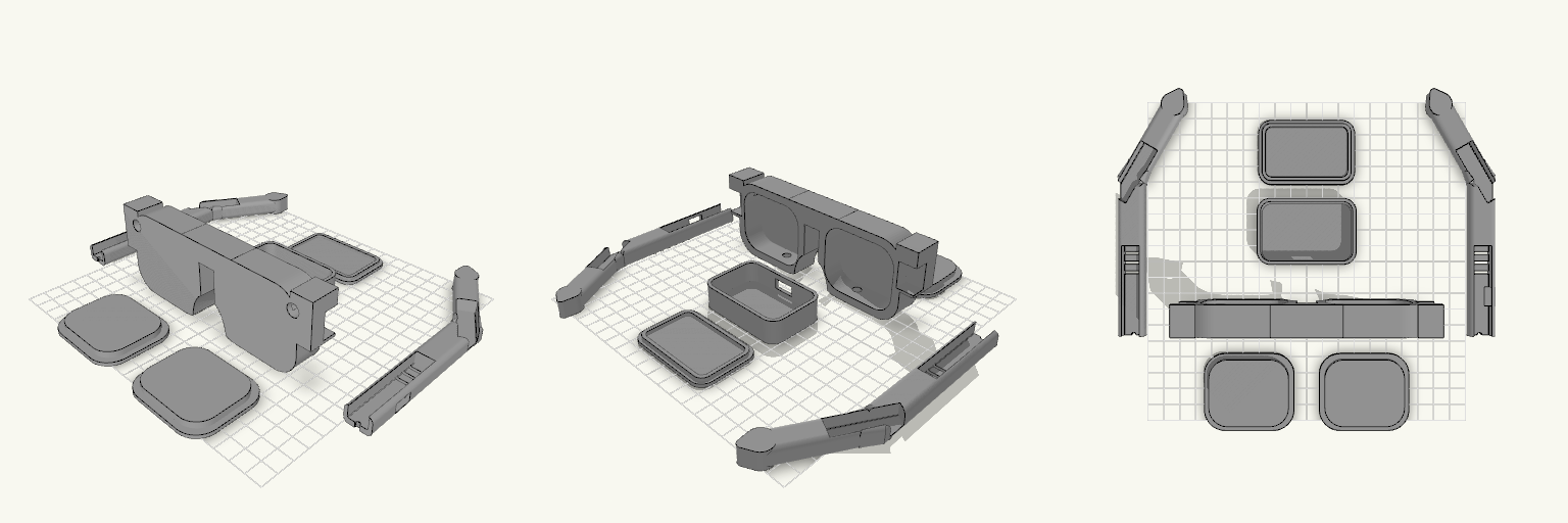
A wearable housing for smart-glasses electronics, with a chunky sci-fi visor silhouette: twin rounded lens bays, front camera ports, and downward sensor holes. Hollow temple arms hold speakers and haptics, and a separate electronics box carries the main board. The frame now comes with two cover caps that close the rear eye cavities, so the electronics inside stay protected. Design notes Frame caps: 56 x 48 mm plates with a plug lip that seats in each eye cavity Camera ports: 8 mm wide, 24 mm deep Electronics box with its own lipped lid Arms hinge with 3 mm pins or filament offcuts Prints as separate flat parts, no supports needed
バルブ、サーボケース(仮)
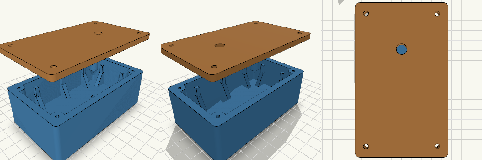
A small bunker of a box: thick walls braced by tapered buttress ribs, a ribbed underside, and a flat screw-down lid that lifts straight off the top. Built as a housing for a servo-driven rotary valve, with a completely empty interior. Design notes Size: 60 × 100 × 40 mm overall, including the lid and all ribs. Ribs: tapered gusset-style ribs on all four walls, plus underside ribs the body stands on when printing. Corners: rounded, with four blended screw bosses that double as corner reinforcement. Lid: 4 mm, with countersunk M3 clearance holes into pilot holes in the bosses. Hose holes: 6 mm, on one shared vertical axis; the Y and X positions are editable parameters (Y defaults to 20 mm off centre). Floor: flat and clear of obstructions.