Heatwave Backrest Ice Pack Holster
Created today
Description
A cooling pocket for the sweatbox season: this holster turns a standard 150 x 100 mm gel ice pack into a chair-back accessory. The pack slides in from the top, sits behind a 5 mm lip that frames the front window, and presses its cold face against your back while the shell keeps it from sliding out. Two slots through the back plate take a velcro strap, so the whole rig cinches around the chair's backrest post.
Design notes
- Pocket: 152 x 102 mm inside, with room for a pack about 14 mm thick.
- Lip: 5 mm all the way around the front window, so the pack stays put.
- Strap slots: two 26 mm wide slots through the back plate, set at roughly a quarter and three quarters of the height.
- Shell: 2.5 mm walls, 3 mm rounded side edges, and a 3 mm back plate.
- Overall size: about 157 x 19.5 x 107 mm.
Pairs well with
- A hook-and-loop strap wide enough to pass through a 26 mm slot
- Flexible gel packs, which sit more comfortably than rigid ones
- Remix idea: closing the top edge partway with a lower retaining bar
Images
More like this
Explore more in Desk & Tech →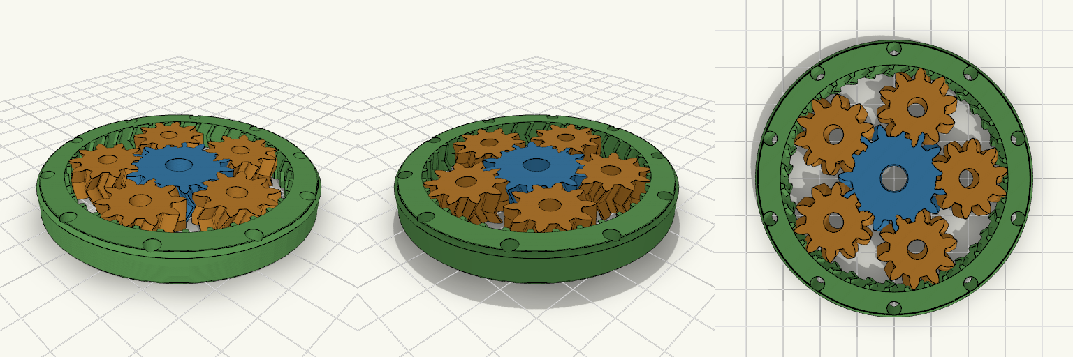
Fidget Spinner Planetario Ø70 mm
Fidget spinner a ingranaggi planetari stampabile in un solo pezzo (print-in-place), diametro esterno 70 mm, con ingranaggio solare centrale, 5 satelliti e anello esterno dentato internamente. L'anello è alleggerito da 10 fori passanti e non ha coperchi, così gli ingranaggi restano visibili. Diametro esterno: 70 mm, spessore 8 mm Modulo 1,5; solare 15 denti, satelliti 10 denti, corona 35 denti Denti elicoidali a spina di pesce (25°) che trattengono i satelliti senza assi Gioco sui denti: 0,25 mm Fori centrali Ø7 mm (solare) e Ø5 mm (satelliti) per alleggerire Stampa piatta, senza supporti; PLA o PETG
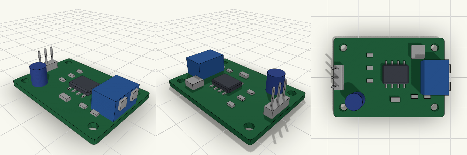
SPET Driver Module
A postage-stamp-sized green driver board in the spirit of a classic hobby breakout module. It stands in for a smart tap's SPET driver stage: a 35 × 25 mm PCB carrying a placeholder driver IC, a few passives, a capacitor, an inductor, and an LED. The exact circuit is deliberately left generic. Supply: 5 V DC via a 3-pin 2.54 mm input header (5V, GND, signal) on the left edge. Output: 2-position terminal block on the right edge. Mounting: four 2.5 mm holes, 3 mm in from each corner. Height: tallest part is the terminal block, about 7.6 mm above the board base. Remix hooks: the parameters at the top of the file and each component module can be swapped for the real parts.
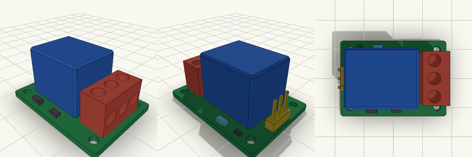
5V Single-Channel Relay Module
A 35 × 25 × 1.6 mm single-channel 5 V relay module for switching a solenoid valve from a compatible control circuit. It carries a blue 19 × 15.5 × 15.5 mm relay housing, a 3-pin control header, a 3-position screw terminal block for the switched load, an indicator LED and basic switching parts, with four 2.5 mm mounting holes. Remix hooks Board size: pcbl and pcbw (35 × 25). Going to 50 × 26 gives a conventional layout with more room around the relay. Relay body: relayl, relayw, relayh (19 × 15.5 × 15.5) and relayx/relay_y. Swap in the dimensions of the real part. Connector positions: hdrx, hdrpitch, hdrn for the control header (VCC, GND, IN, 2.54 mm pitch); termx, termpitch, termn for the load terminals (COM, NO, NC, 5.08 mm pitch). Mounting holes: holed (2.5) and holeinset (3). Colour coding: yellow header is low-voltage control, red terminals are the switched load. Keep them visually distinct in any variant. Pairs with: an enclosure with roughly 17.5 mm of clearance above the board, standoffs on the four holes, and a flyback-protected solenoid valve. The LED, transistor, diode and resistor are placeholders for layout, not a specific circuit.
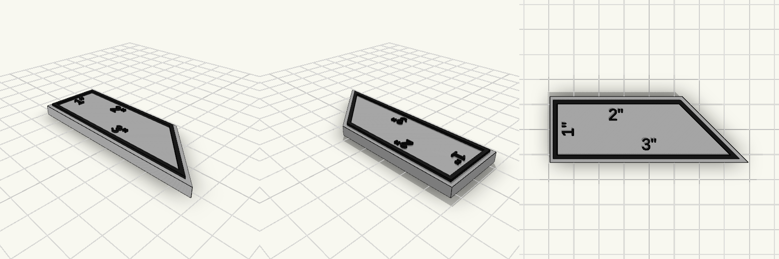
Rectangular Trapezoid Ruler, White and Black
A rectangle-style trapezoid ruler with a white body and a black outline and labels raised on top, sized to 1", 2" and 3" sides. Bottom edge 3", left edge 2", top edge 1", with one slanted corner White base 4 mm thick, black outline and labels raised 1 mm (5 mm total) Outline set slightly inward from the edge, leaving a thin white border Only the 1", 2" and 3" lengths are labelled; no tick marks Suited to a two-colour print, with the black layer printed on top of the white base.
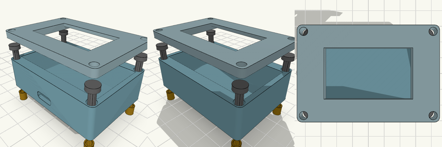
ESP32 Enclosure with 1.3 Inch OLED Lid
Two-piece enclosure for a 30-pin ESP32-WROOM-32 DevKit V1 with a 1.3 inch SH1106 OLED mounted in the lid. Shown exploded with heat inserts and M3 screws aligned to the corner holes. The lid has a 35.5 x 34.5 mm recess on the underside that holds the OLED PCB, and a 35.5 x 20.5 mm window through the front panel for the visible display area. ESP32 pocket: 52 x 28 mm, 14 mm deep Outer size: about 56.8 x 40.4 mm, 2.4 mm walls Front USB-C slot, 10 x 4 mm Four corner screw holes for M3 screws and heat inserts Front panel thickness behind the window: 1.6 mm Print the lid face-down for a clean front surface.
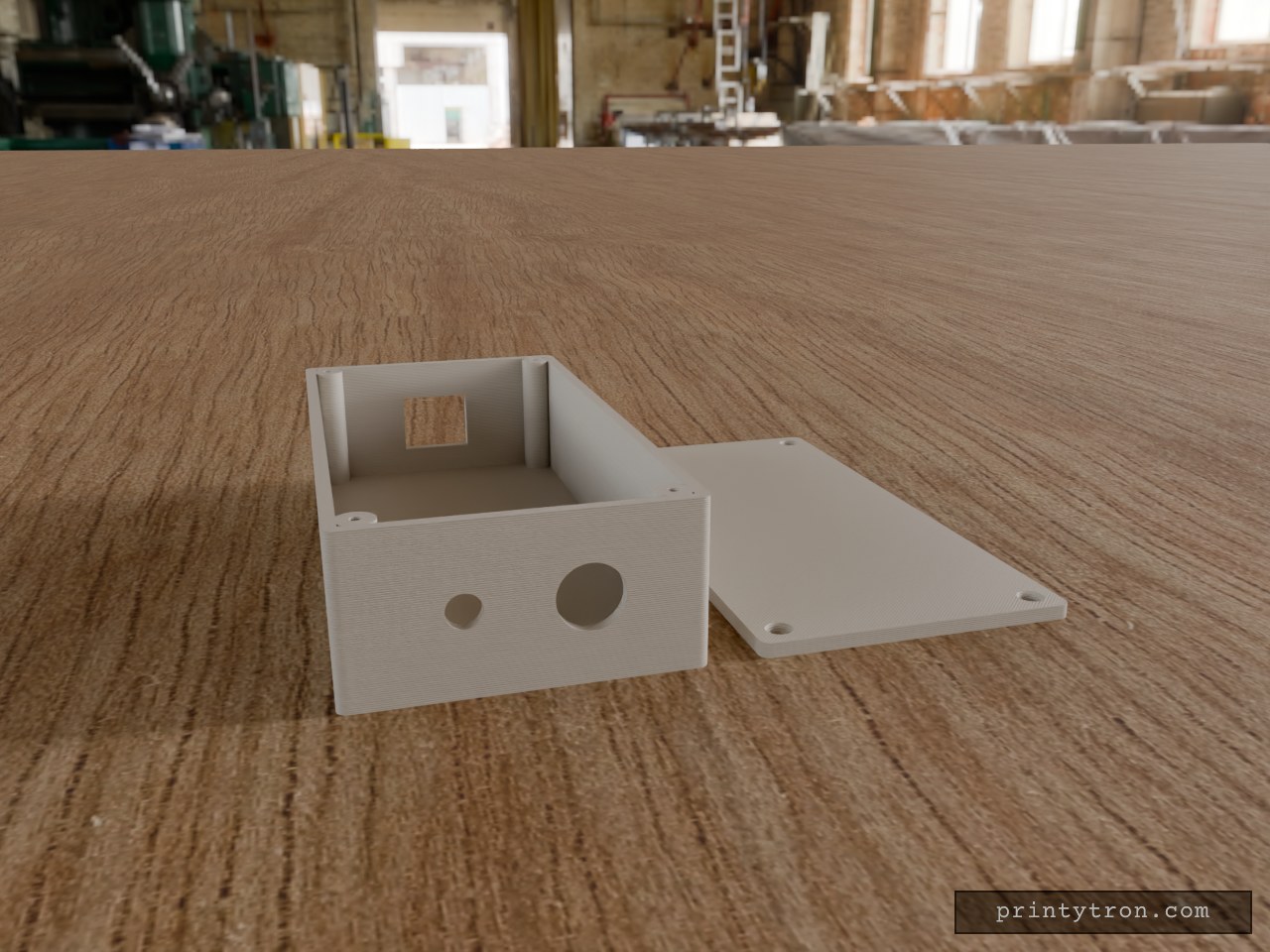
Bulkhead Signal Box with RJ45 and SMA
A compact 130 × 65 × 35 mm enclosure in the spirit of a field-radio interface box: Ethernet in one end, antenna and cable gland out the other. The lid sits flush and is held by four M2.5 × 10 mm countersunk screws threading into corner posts. RJ45 end: 16.5 × 14 mm rectangular opening, centred in width and height. Other end: 6.5 mm hole for a through-mount SMA connector and a 12.5 mm hole for a PG7-style cable gland, spaced evenly across the 65 mm width and centred in height. Walls: 2.5 mm; lid 3 mm, printed flat beside the box. Screws: 2.1 mm pilot holes in the posts for self-tapping M2.5; countersunk clearance holes in the lid.