5V Single-Channel Relay Module
Created today
Description
A 35 × 25 × 1.6 mm single-channel 5 V relay module for switching a solenoid valve from a compatible control circuit. It carries a blue 19 × 15.5 × 15.5 mm relay housing, a 3-pin control header, a 3-position screw terminal block for the switched load, an indicator LED and basic switching parts, with four 2.5 mm mounting holes.
Remix hooks
- Board size:
pcb_landpcb_w(35 × 25). Going to 50 × 26 gives a conventional layout with more room around the relay. - Relay body:
relay_l,relay_w,relay_h(19 × 15.5 × 15.5) andrelay_x/relay_y. Swap in the dimensions of the real part. - Connector positions:
hdr_x,hdr_pitch,hdr_nfor the control header (VCC, GND, IN, 2.54 mm pitch);term_x,term_pitch,term_nfor the load terminals (COM, NO, NC, 5.08 mm pitch). - Mounting holes:
hole_d(2.5) andhole_inset(3). - Colour coding: yellow header is low-voltage control, red terminals are the switched load. Keep them visually distinct in any variant.
- Pairs with: an enclosure with roughly 17.5 mm of clearance above the board, standoffs on the four holes, and a flyback-protected solenoid valve.
The LED, transistor, diode and resistor are placeholders for layout, not a specific circuit.
Images
More like this
Explore more in Desk & Tech →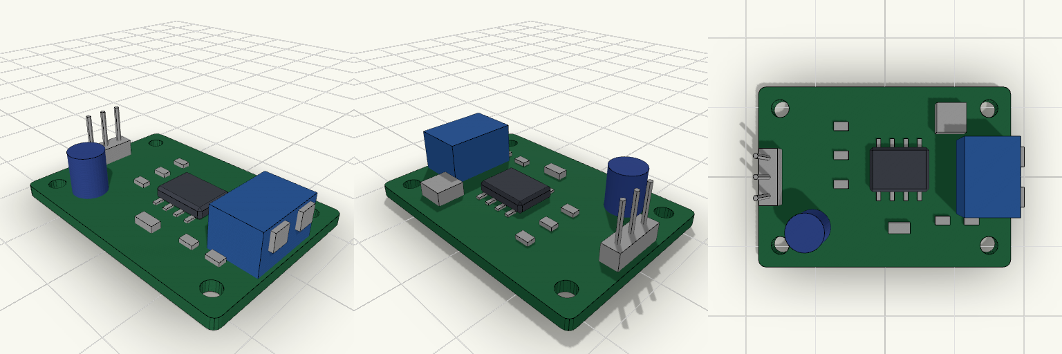
SPET Driver Module
A postage-stamp-sized green driver board in the spirit of a classic hobby breakout module. It stands in for a smart tap's SPET driver stage: a 35 × 25 mm PCB carrying a placeholder driver IC, a few passives, a capacitor, an inductor, and an LED. The exact circuit is deliberately left generic. Supply: 5 V DC via a 3-pin 2.54 mm input header (5V, GND, signal) on the left edge. Output: 2-position terminal block on the right edge. Mounting: four 2.5 mm holes, 3 mm in from each corner. Height: tallest part is the terminal block, about 7.6 mm above the board base. Remix hooks: the parameters at the top of the file and each component module can be swapped for the real parts.
マイコンケース
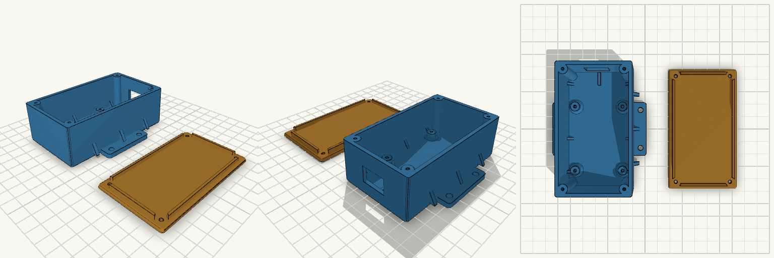
A two-part enclosure for a 47 × 57 mm STM32F103 board, with a screw-down lid, external mounting flanges and a cable opening at the connector end. The base has 2.5 mm walls, four board bosses at 37 × 50 mm spacing holding the board 5 mm above the floor, and four corner posts for the lid screws. The lid has a locating lip and four clearance holes. Triangular gussets reinforce the flange-to-wall joints and the wall-to-floor joints, and the internal corners are rounded. Total height with lid: 35 mm Connector end extended 20 mm (+Y), with an adjustable cable opening Lid screws: M2.5 self-tapping, 2.2 mm pilot holes in the corner posts Adjustable: hole spacing and offset, boss height and hole size, flange hole size and positions, cable opening, extensions Board hole spacing is approximate and should be checked against the real board
Phone Stand with Cable Channel
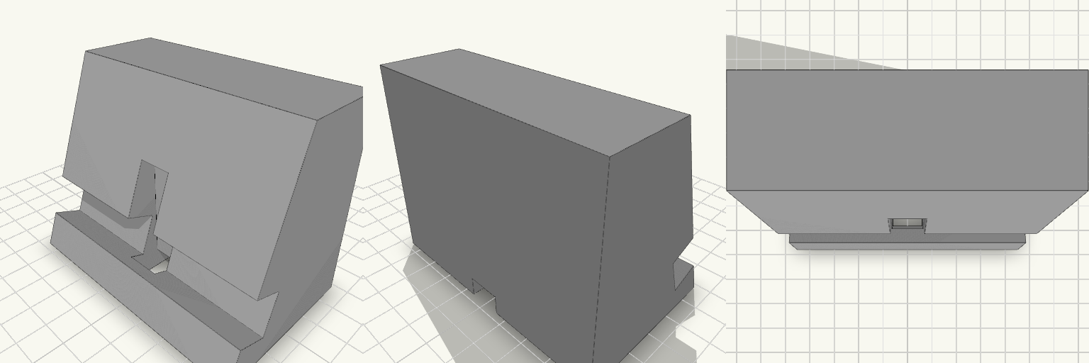
A phone stand that holds the phone upright in portrait or landscape, with a cable channel so the charger doesn't pin the phone down or dangle off the edge. Most stands either tip the phone back too far to tap or force the cable to loop around the outside. This one leans the phone at 70° from horizontal and routes the cable up through the stand to the back of the phone. What decides fit and print Lean angle: 70° from horizontal, steep enough to tap the screen and upright enough to watch video. Groove: runs the full 90 mm width, so the phone sits in it in either orientation. It is sized for a phone in a thin case. Cable channel: 12 mm wide, open on the underside of the base. It runs in from the back, then rises through a 12 x 12 mm opening in the groove floor. Overall size: 90 mm wide, about 56 mm deep and 70 mm tall. Printing: the flat base goes down on the bed. The underside channel is a 7 mm-tall tunnel, so print it with bridging on or light supports. No other supports are needed. Material: PLA or PETG both work. Use 3 or more perimeters for a stiffer groove lip.
Fidget Spinner Planetario Ø70 mm
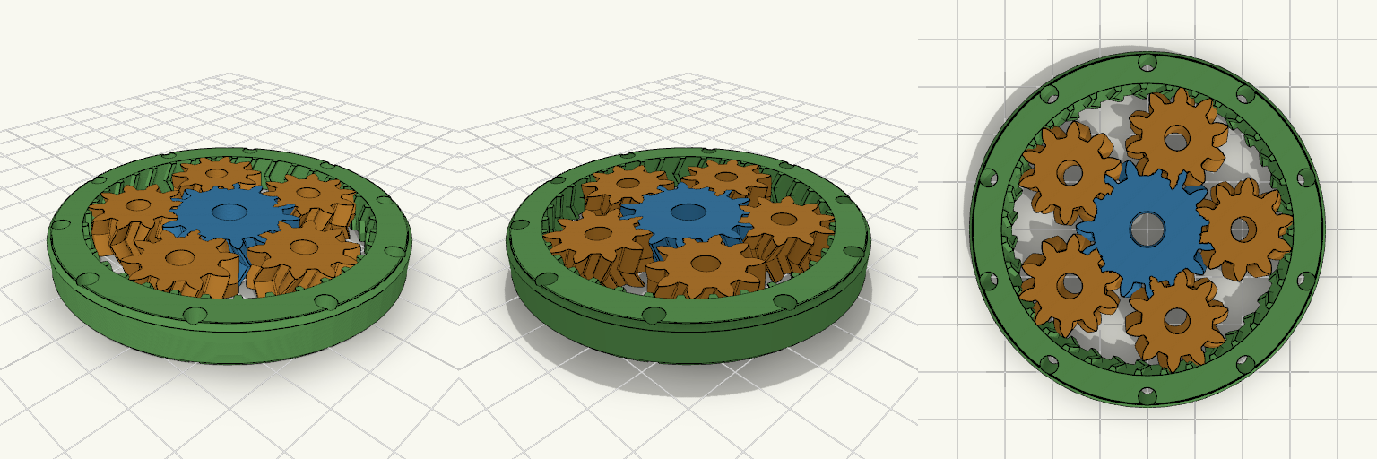
Fidget spinner a ingranaggi planetari stampabile in un solo pezzo (print-in-place), diametro esterno 70 mm, con ingranaggio solare centrale, 5 satelliti e anello esterno dentato internamente. L'anello è alleggerito da 10 fori passanti e non ha coperchi, così gli ingranaggi restano visibili. Diametro esterno: 70 mm, spessore 8 mm Modulo 1,5; solare 15 denti, satelliti 10 denti, corona 35 denti Denti elicoidali a spina di pesce (25°) che trattengono i satelliti senza assi Gioco sui denti: 0,25 mm Fori centrali Ø7 mm (solare) e Ø5 mm (satelliti) per alleggerire Stampa piatta, senza supporti; PLA o PETG
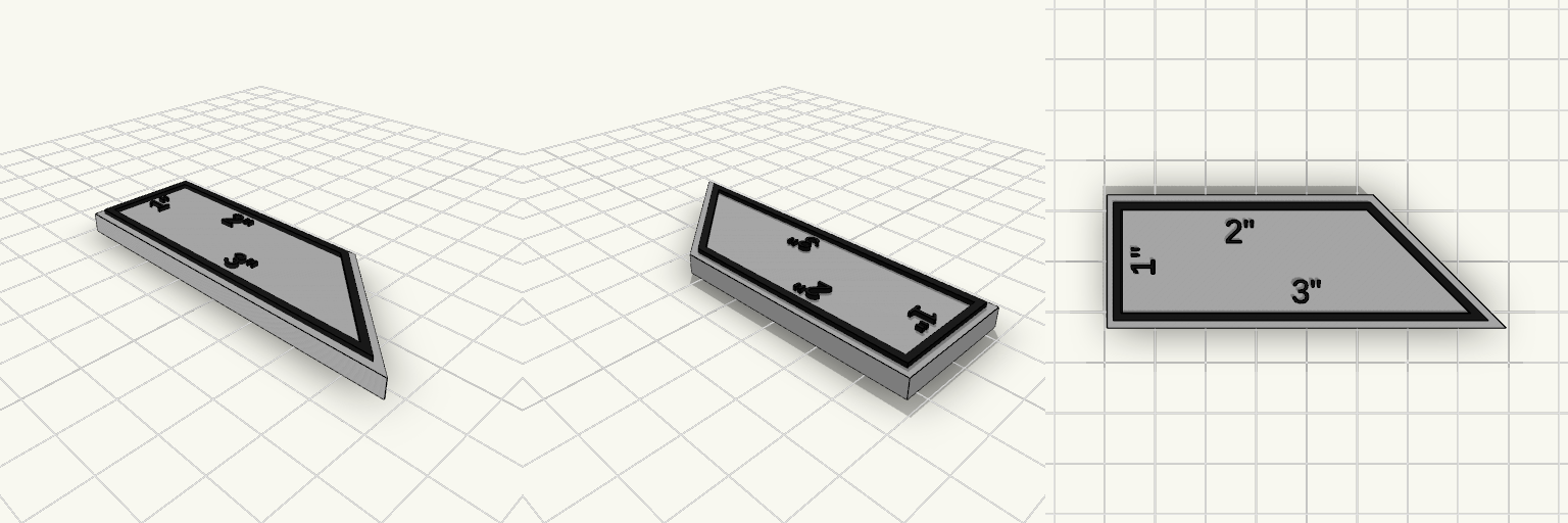
Rectangular Trapezoid Ruler, White and Black
A rectangle-style trapezoid ruler with a white body and a black outline and labels raised on top, sized to 1", 2" and 3" sides. Bottom edge 3", left edge 2", top edge 1", with one slanted corner White base 4 mm thick, black outline and labels raised 1 mm (5 mm total) Outline set slightly inward from the edge, leaving a thin white border Only the 1", 2" and 3" lengths are labelled; no tick marks Suited to a two-colour print, with the black layer printed on top of the white base.
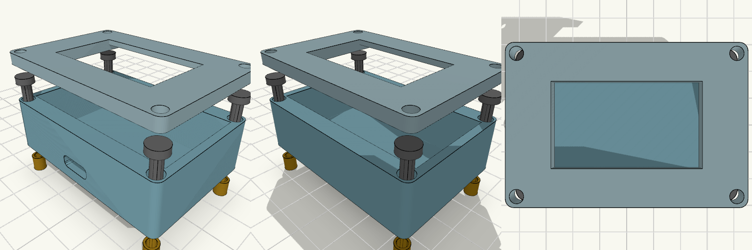
ESP32 Enclosure with 1.3 Inch OLED Lid
Two-piece enclosure for a 30-pin ESP32-WROOM-32 DevKit V1 with a 1.3 inch SH1106 OLED mounted in the lid. Shown exploded with heat inserts and M3 screws aligned to the corner holes. The lid has a 35.5 x 34.5 mm recess on the underside that holds the OLED PCB, and a 35.5 x 20.5 mm window through the front panel for the visible display area. ESP32 pocket: 52 x 28 mm, 14 mm deep Outer size: about 56.8 x 40.4 mm, 2.4 mm walls Front USB-C slot, 10 x 4 mm Four corner screw holes for M3 screws and heat inserts Front panel thickness behind the window: 1.6 mm Print the lid face-down for a clean front surface.