Description
A compact field-radio enclosure in the spirit of a pocket survey instrument: the board sits beside a spring-loaded battery holder, with the screen showing through a window in the lid.
- Fits an 81 × 21 × 20 mm spring-loaded battery holder
- 26 mm overall height with the lid installed
- USB-C slot sized for a 8.98 × 3.2 mm port
- Two lid holes above the board's push buttons, ready for TPU plungers
- Centred antenna hole and 12 mm power button hole on the end wall
Images
More like this
Explore more in Desk & Tech →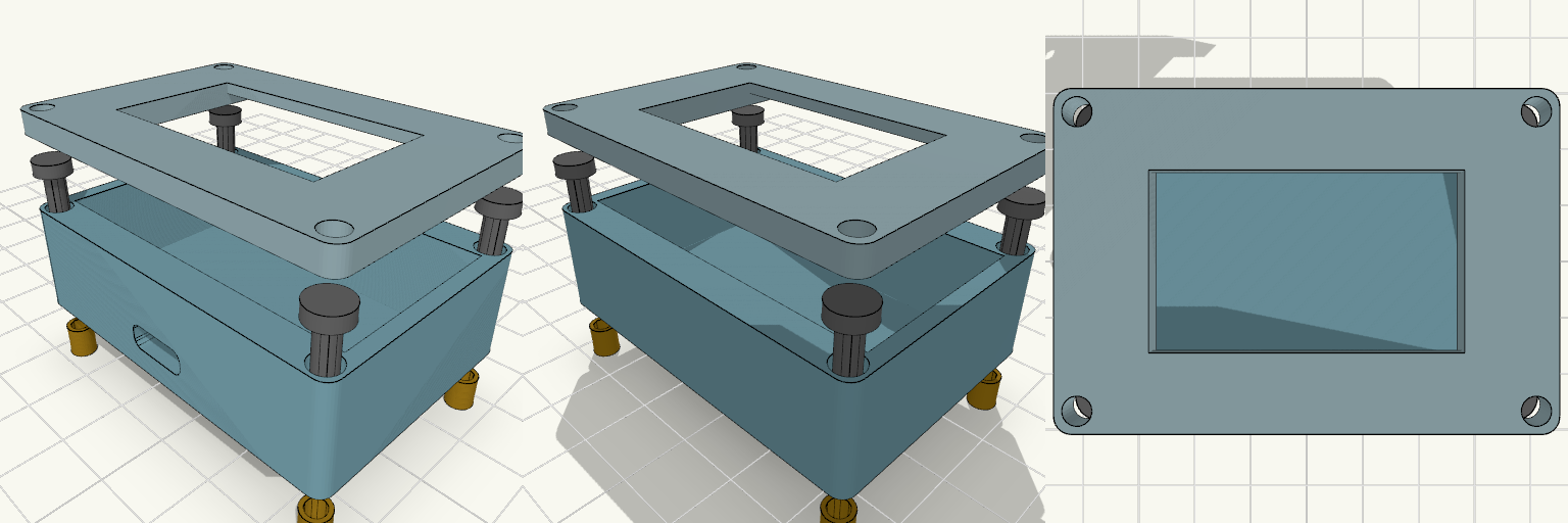
ESP32 Enclosure with 1.3 Inch OLED Lid
Two-piece enclosure for a 30-pin ESP32-WROOM-32 DevKit V1 with a 1.3 inch SH1106 OLED mounted in the lid. Shown exploded with heat inserts and M3 screws aligned to the corner holes. The lid has a 35.5 x 34.5 mm recess on the underside that holds the OLED PCB, and a 35.5 x 20.5 mm window through the front panel for the visible display area. ESP32 pocket: 52 x 28 mm, 14 mm deep Outer size: about 56.8 x 40.4 mm, 2.4 mm walls Front USB-C slot, 10 x 4 mm Four corner screw holes for M3 screws and heat inserts Front panel thickness behind the window: 1.6 mm Print the lid face-down for a clean front surface.
Arcade Console Desk Clock Case
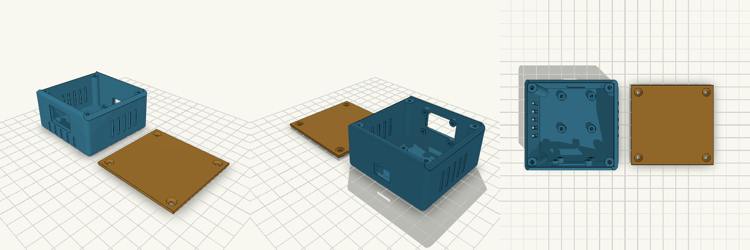
A compact desk-clock enclosure with a gaming-rig attitude: chamfered shoulders, vented flanks and grooved front stripes under the OLED window, like a mini console from a late-night LAN party. Window for a 0.96" OLED on the front Standoffs for an ESP32 WROOM-32 devkit USB slot at the back Four corner screw bosses and a separate screw-on lid Side vent slots for airflow
Platinenabdeckung 20x20 mm mit Öse
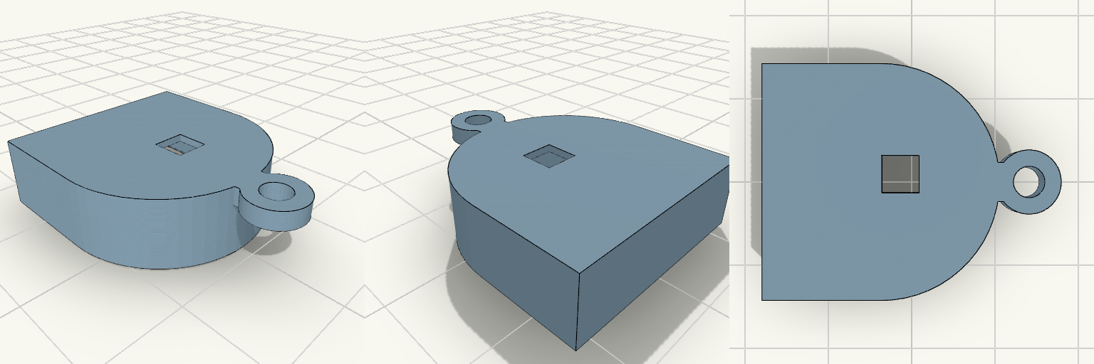
Abdeckung für eine 20×20×4 mm große D-förmige Platine mit Einrastnasen, Tasteröffnung und Schnuröse an der Rundung. Gesamthöhe 7,8 mm, Decke 0,8 mm, Wandstärke 1,8 mm Tasteröffnung 3,8 × 3,8 mm Öse: 6,5 mm Außendurchmesser, 3,2 mm Bohrung, 2 mm dick, bündig mit der Oberseite Öse sitzt mittig an der Rundung (Y = 0) auf der +X-Seite Empfohlen: transparentes PETG oder PLA
SPET Driver Module
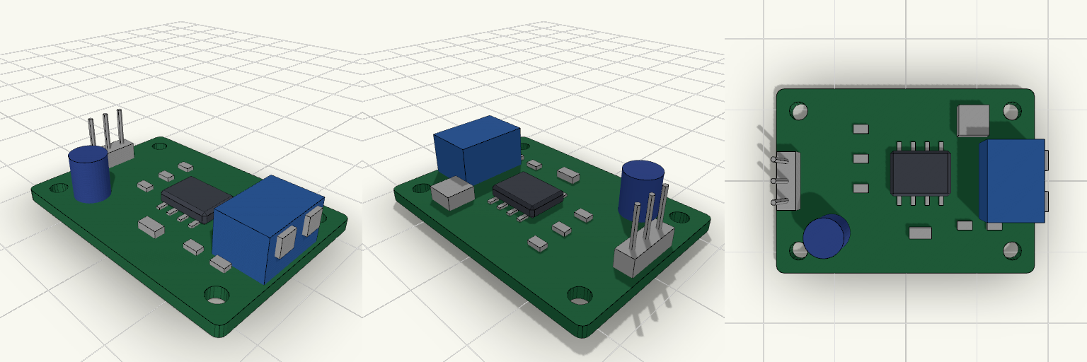
A postage-stamp-sized green driver board in the spirit of a classic hobby breakout module. It stands in for a smart tap's SPET driver stage: a 35 × 25 mm PCB carrying a placeholder driver IC, a few passives, a capacitor, an inductor, and an LED. The exact circuit is deliberately left generic. Supply: 5 V DC via a 3-pin 2.54 mm input header (5V, GND, signal) on the left edge. Output: 2-position terminal block on the right edge. Mounting: four 2.5 mm holes, 3 mm in from each corner. Height: tallest part is the terminal block, about 7.6 mm above the board base. Remix hooks: the parameters at the top of the file and each component module can be swapped for the real parts.
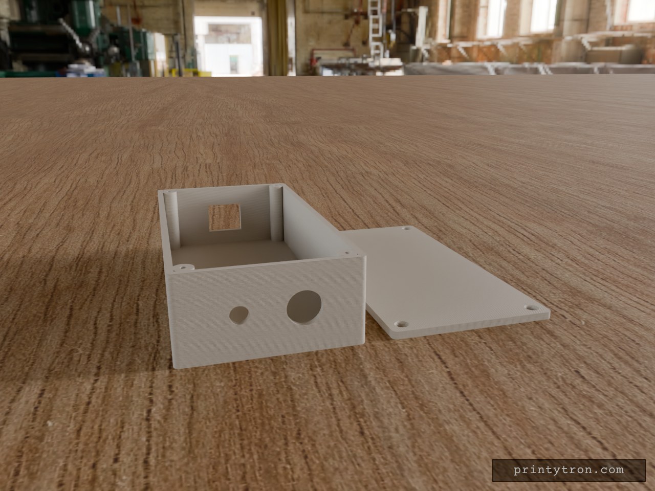
Bulkhead Signal Box with RJ45 and SMA
A compact 130 × 65 × 35 mm enclosure in the spirit of a field-radio interface box: Ethernet in one end, antenna and cable gland out the other. The lid sits flush and is held by four M2.5 × 10 mm countersunk screws threading into corner posts. RJ45 end: 16.5 × 14 mm rectangular opening, centred in width and height. Other end: 6.5 mm hole for a through-mount SMA connector and a 12.5 mm hole for a PG7-style cable gland, spaced evenly across the 65 mm width and centred in height. Walls: 2.5 mm; lid 3 mm, printed flat beside the box. Screws: 2.1 mm pilot holes in the posts for self-tapping M2.5; countersunk clearance holes in the lid.
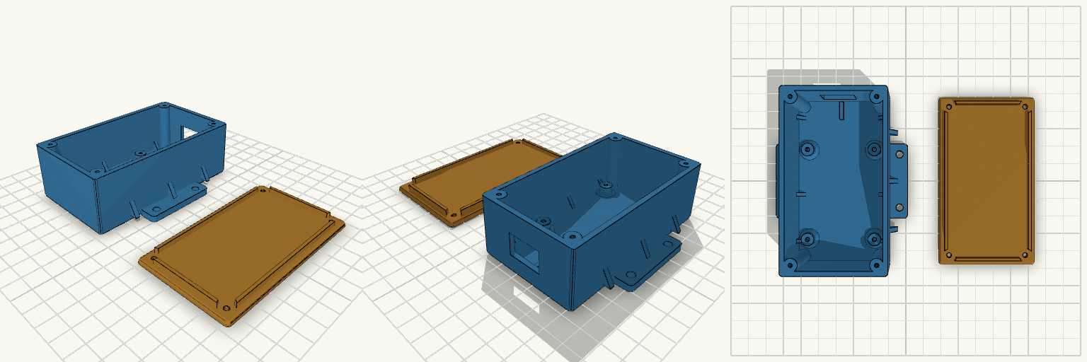
マイコンケース
A two-part enclosure for a 47 × 57 mm STM32F103 board, with a screw-down lid, external mounting flanges and a cable opening at the connector end. The base has 2.5 mm walls, four board bosses at 37 × 50 mm spacing holding the board 5 mm above the floor, and four corner posts for the lid screws. The lid has a locating lip and four clearance holes. Triangular gussets reinforce the flange-to-wall joints and the wall-to-floor joints, and the internal corners are rounded. Total height with lid: 35 mm Connector end extended 20 mm (+Y), with an adjustable cable opening Lid screws: M2.5 self-tapping, 2.2 mm pilot holes in the corner posts Adjustable: hole spacing and offset, boss height and hole size, flange hole size and positions, cable opening, extensions Board hole spacing is approximate and should be checked against the real board