Phone
Created 18 days ago
Description
A calculator-shaped phone case styled after the TI-30Xa, with the top shell hinged along the right long edge so it folds open like a book and lies back behind the bottom shell, exposing the whole phone. Lay the phone screen-up in the bottom shell, close the top, and it clicks shut on the other three sides; the screen sits behind an oversized 66 × 42 mm window where the LCD would be. The keypad is 40 recessed divots in a 5 × 8 grid, with the buttons printed as a separate set 0.5 mm smaller on each side so they drop in and sit slightly proud. A camera opening sits in the back of the bottom shell, "TI-30Xa SOLAR" is engraved above the window, and a separate hinge pin runs the full length of the hinge. It prints as four separate parts: bottom shell, top shell, buttons and hinge pin.
Remix hooks
- Shells: each about 96 × 176 mm on the plate; the top shell is 11.5 mm thick and the bottom shell 10.5 mm. The 176 mm length is the real constraint — shorten it and the 5 × 8 button grid has to lose rows, and the hinge spacing follows the same length.
- Hinge: a full-length piano hinge set into a notch along the right edge, so nothing protrudes past the outline. Five knuckles about 7 mm across, three on one half and two on the other, with 0.5 mm gaps and round clearance cutouts where the opposite knuckles pass. The body is a little wider overall to swallow it. This is the part worth redesigning first: move the notch to the left edge for a left-handed fold, or lengthen the knuckles for more stiffness.
- Hinge pin: 3 mm thick with a 5.5 mm head, 174.5 mm long, running in 3.5 mm holes and stopped by a closed end so it cannot slide through. Print it lying flat. A 3 mm metal rod is a direct drop-in substitute if you want it tougher.
- Phone cavity: 80 × 165 mm and 10 mm deep, closed at both ends when shut. That clears an iPhone 17 (about 71.5 mm wide) and the Pro Max sizes (about 77.6 mm). This is the first number to touch for fit; narrowing toward 76 mm tightens things up for standard phones, and going past about 82 mm starts to thin the side walls.
- Screen window: 66 × 42 mm, deliberately oversized so the cutout does not fight the phone's own bezels. Shrink it to hide more of the display, grow it for more live screen.
- Camera opening: 48 × 42 mm in the back of the bottom shell, sized around a large camera bump — a smaller phone just gets extra opening, so this is a safe one to trim down to your own lens.
- Button divots: 12.5 × 9.5 mm, 1.2 mm deep, in a 5 × 8 grid; the separate button set lays out on a 73.5 × 99.5 mm plate at 11.5 × 8.5 mm each — 0.5 mm clearance per side — so they drop in without binding and sit slightly proud. Deepen the divots to 1.6 mm if you want them flush.
Obvious directions to take it: swap the uniform 5 × 8 grid for a true TI-30Xa layout, engrave the legends onto the buttons instead of leaving them blank, add a raised lip around the rear camera opening, add a lanyard loop, or print the shells in contrasting colours. The snap closure is the easiest thing to tune — deepen or shave the rim bumps if the lid is too tight or too loose. It pairs well with a second-colour button set and with any phone that fits the slot dimensions above.
Images
More like this
Explore more in Desk & Tech →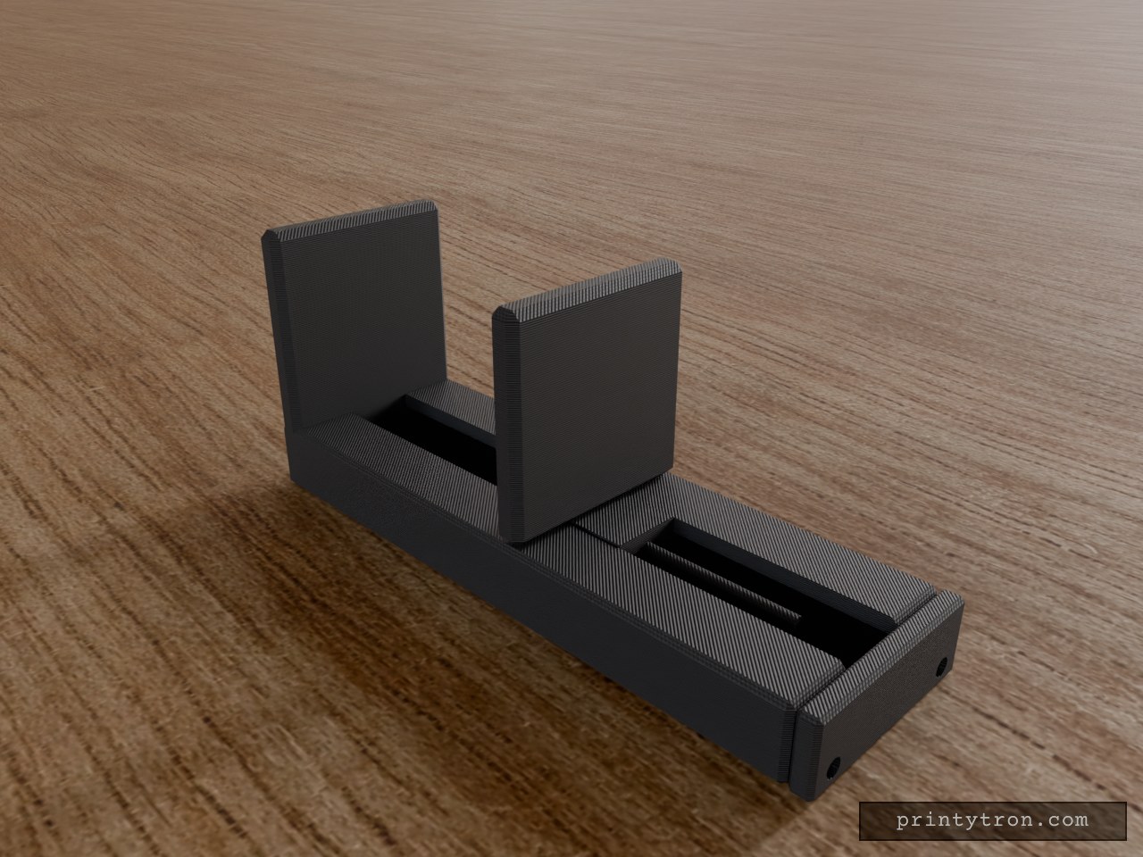
1/4-20 Tripod Spring Phone Clamp, 60–85mm
This is a spring-loaded phone clamp for a standard 1/4-20 tripod mount. It has a fixed jaw, a sliding jaw and a screw-on end cap. The base has a hex pocket that holds a 7/16 in across-flats 1/4-20 nut, with a 6.8 mm bore above it for the tripod screw. What it fits Phones 60–85 mm wide, measured across the body including any case, in portrait orientation. Tripod heads with a 1/4-20 UNC male stud. This is the common camera and phone tripod standard. Jaw faces are chamfered on the inner edges so they don't mar the phone. Check before printing Measure your nut across the flats. The pocket is sized for a 7/16 in (11.1 mm) hex 1/4-20 nut. A nut with a different flat size will rattle or won't seat. Hardware you supply 1 × 1/4-20 hex nut, 7/16 in across flats. 1 × compression spring, about 6 mm OD and 45 mm free length, over the slider's 3 mm guide rod. 2 × M3 screws for the end cap. The pilot holes are 2.6 mm. Does not fit Phones narrower than 60 mm or wider than 85 mm. Metric tripod studs such as 3/8 in or M6. The bore is sized only for 1/4-20. Landscape use on very heavy phones. Spring force is untested, and it is lowest near the 85 mm end. A heavy phone in a thick case may be loose there. Parts Base and fixed jaw Sliding jaw End cap
Phone Clamp 60-85mm with 1/4-20 Socket
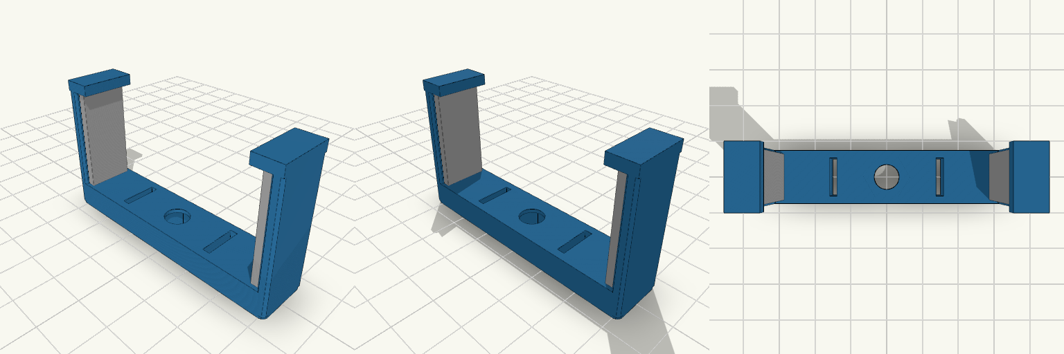
U-shaped spring clamp that holds a phone across its back and bolts to the centre screw of a ring light. The two jaws grip the phone's long edges. The rest opening is 58 mm and the jaws flex to about 85 mm. Separate soft pads sit on the inner faces to protect the phone's edges. The base has a 1/4-20 through hole with a hex nut pocket on the underside. Two slots cut into the base give the jaws room to spring. Each jaw ends in a retaining lip that stops the phone from lifting out. Specs Opening: 60-85 mm, 58 mm at rest Mount: 1/4-20 through hole (6.6 mm) with a 12.2 mm hex nut pocket Jaw thickness: 2.6 mm Jaw width: 22 mm Overall size: about 63 x 14 x 36 mm Clamp body material: PETG suggested, for spring flex Pad material: TPU suggested, printed as separate pieces Spring travel: not tested, so check the flex before loading a phone Use cases: ring light phone mount, filming, content creation setups
Octobay — 5.25" to 3.5" Drive Cage
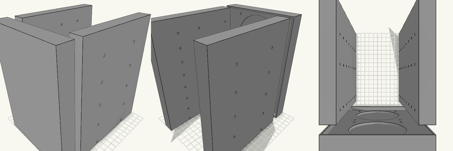
Octobay turns a five-bay stack of half-height 5.25" slots into room for eight 3.5" drives, and adds a 25 mm front cage that carries two 92 mm fans. The outer side faces take M3 heat-set inserts, so the whole cage screws into the case's 5.25" rails instead of resting on them. Everything is one printed part: the drive stack, the side mounting blocks and the fan cage print as a single body. Because the fans close off the front, drives now load from the back. The fan cavity behind the grille is hollow, so air still passes through to the drive stack. Dimensions Overall: 145 mm wide × 197.5 mm deep × 205.5 mm tall Fits: five half-height 5.25" bays Holds: eight 3.5" drives, stacked vertically Drive channel: 102.6 mm wide — 1 mm of play around a 101.6 mm drive Mounting 20 insert holes, 10 per side, for M3 heat-set inserts — 4.2 mm across and 6 mm deep Two insert holes per bay, at 41.3 and 117.5 mm from the front, 6.35 mm above each bay floor Solid blocks sit behind each hole to give the inserts something to bite into Three M3 screw holes per side per drive, at 14, 76.6 and 117.6 mm from the front Cross ribs sit clear of the screw holes so a screwdriver can reach every fastener Fan cage Two 92 mm fans, stacked vertically on the 25 mm front section 88 mm fan openings with 4.4 mm screw holes on the standard 82.5 mm square pattern Hollow cavity behind the fans feeds air to the drive channels Print notes Drive channels are open at the back, top and bottom, and the gaps between the inner and outer side walls are open for cable routing. Screw and insert positions and the 205.5 mm height follow common 5.25" bay standards; they have not been checked against a specific case, so measure your bay rails and drives before printing.
Fidget Slider Toy, Captive Print-in-Place
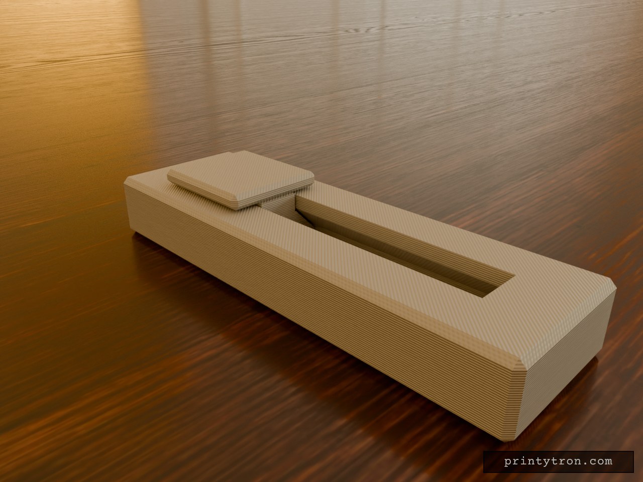
A fidget slider that prints already assembled, so there is no loose weight to lose and nothing to glue. The slider is captured in an enclosed dovetail track and cannot fall out. It runs 40 mm end to end and clicks at each stop instead of rolling freely. What it does Slides back and forth along a closed track in an 80 x 25 mm body. A small bump on the track floor at each end of travel drops into a dimple under the slider and gives the click. The dovetail profile holds the slider down, so it cannot lift out of the rails. Numbers that matter Body: 80 x 25 x 11 mm, with the slider top reaching 14 mm. Slider: 20 mm long, 18 mm wide cap. Travel: 40 mm. Clearance between slider and track: 0.4 mm per side. This is what lets it move after printing. Click bump: about 0.6 mm of interference against the 0.4 mm gap. Reduce the bump height if it feels too stiff. Printing Print flat, body base down, with no supports needed inside the track. Use a well-tuned printer. A 0.4 mm gap fuses easily if the flow is too high. After printing, work the slider back and forth a few times to break any thin bridging between the slider and the rails. Two colours show as separate parts in the preview, but the print is one job.
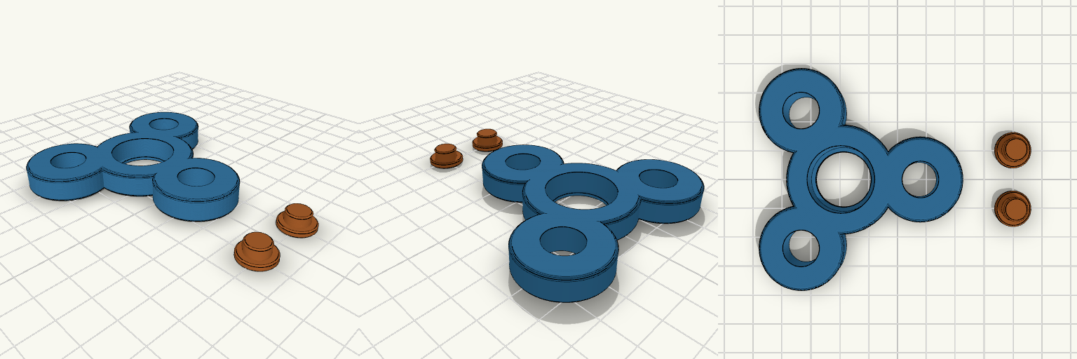
Bearing-Driven Tri-Lobe Fidget Spinner
A classic three-lobe hand spinner, the shape every desk drawer has seen, rebuilt around a real 608 skate bearing so it spins freely for a long time. The body has a bearing pocket in the centre, a lip underneath to hold it, and weight-saving holes in each lobe. Two small caps press into the bearing's inner ring from either side to make the finger pads. Notes You need: one 608 bearing (8 × 22 × 7 mm). Print: body flat; the two caps print flat-side down beside it. No supports. Assembly: press the bearing into the pocket from the top, then push one cap in from each side until they meet. Tuning: if the bearing is loose or tight in the pocket, adjust the pocket diameter slightly. Remix: the lobe holes can be enlarged to take 608 bearings as extra weights.
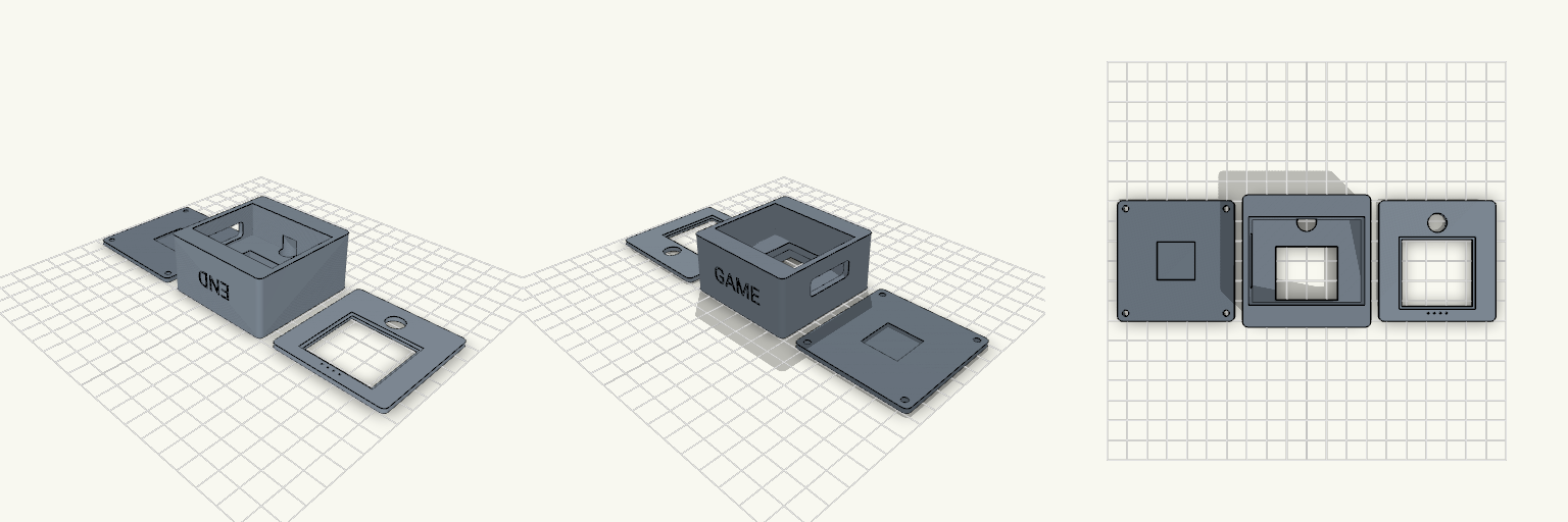
Lockdown — Dev Board Case With Camera Eye
Lockdown is a three-part enclosure for a Freenove ESP32-S3 WROOM CAM board with a 35.5 × 33.5 mm display. The front bezel turns the screen into a face, with a 9.6 mm camera eye above the window. The side wall carries one wide cable opening, so USB-C plugs and cables pass straight through the housing. Features 58 × 60 mm footprint across chassis, back cover and bezel Screen pocket with a support ledge and a flex-cable opening 9.6 mm camera bore lined up with the bezel eye Single 26 × 9 mm cable pass-through on the +X wall, raised for a high-mounted board Four M3 screws from the back Embossed-in END and GAME text on the end walls Print notes Print the three parts flat on their backs. PETG works well.