Description
What it's for
This clip firmly secures a standard 67mm lens cap to a camera strap, keeping it safely out of the dirt during shoots. The rigid cup features a retaining lip to hold the cap tightly around the rim, along with wide cutouts to easily actuate the cap's center-pinch mechanism for quick retrieval. A small, integrated loop on the back allows for threading a paracord tether as a backup safety measure.
Dimensions
- Cap compatibility: Sized for an outer diameter of roughly 67mm and a rim thickness of 7mm.
- Mounting: Built to pass standard flat webbing camera straps through the rear retaining rails.
Remix ideas
- Modify the inner diameter to match alternate filter thread sizes (e.g., 52mm, 58mm, 72mm, or 77mm).
- Adjust the clearance and width of the strap loops to accommodate thicker neoprene straps.
- Enlarge the lanyard loop to accept mini-carabiners or alternative tether hardware.
Images
More like this
Explore more in Desk & Tech →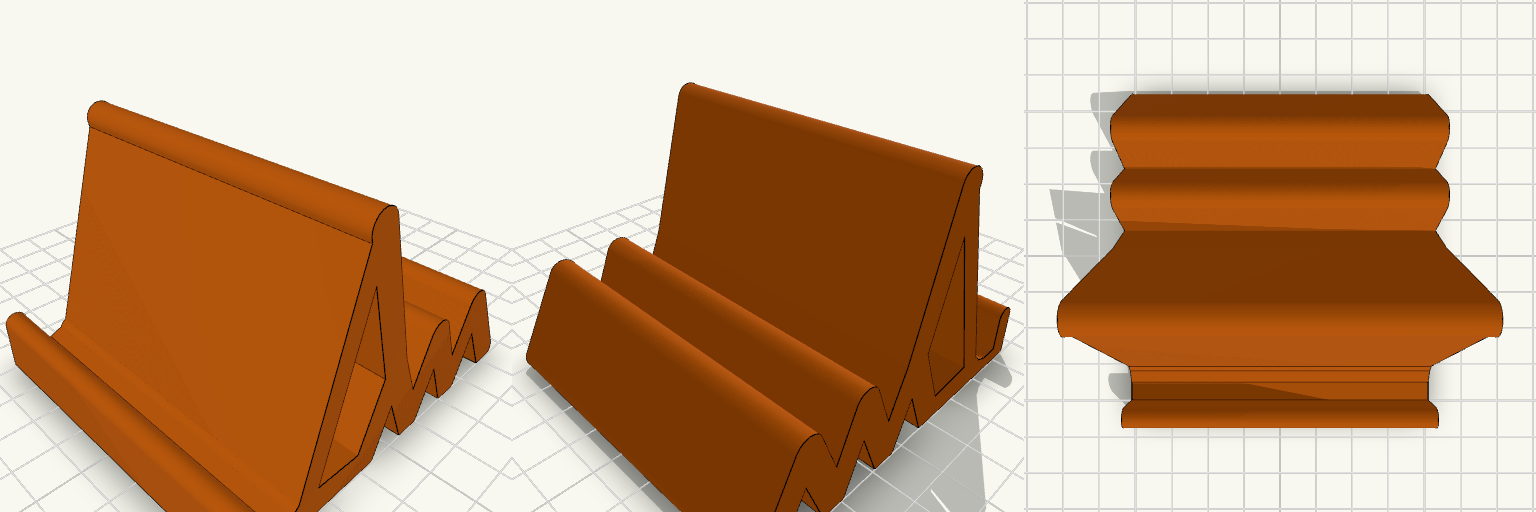
Snake Tail Phone Stand
A one-piece orange phone stand with a low front lip, a short flat seat and a backrest leaning up to about 60 mm. A zig-zag snake of humps runs along the back. Remix hooks Lip height: the front stopper is about 5 mm of strip plus the strip's rounded end, roughly 7.5 mm in total. Raise it for a more secure hold, or lower it further to keep captions clear. Seat depth: 12 mm. Deepen it for thick cases, though a steeper backrest helps more. Backrest angle and height: it rises about 18 mm in Y over 55 mm in Z, so it is steep. Both are easy to change. Snake humps: 4 peaks, each about 14 mm high. Add more humps, or raise or lower the peaks. Width: 70 mm, with a 5 mm strip thickness. Pairs well with a non-slip pad on the seat.
Fidget Spinner Planetario Ø70 mm
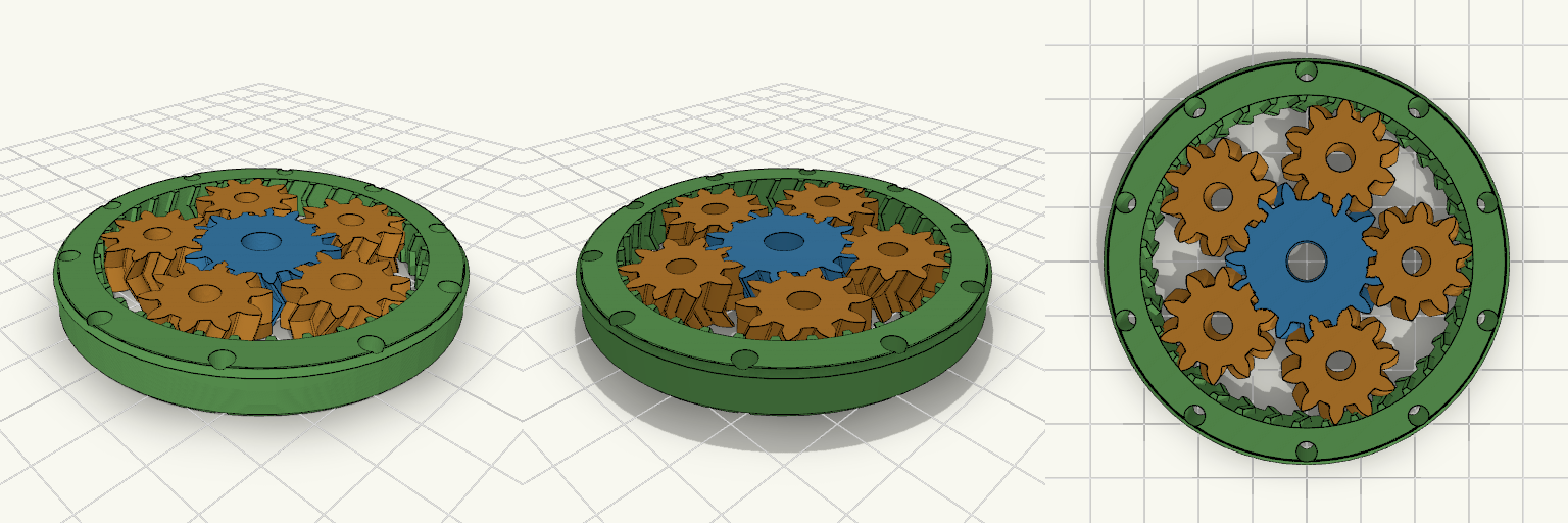
Fidget spinner a ingranaggi planetari stampabile in un solo pezzo (print-in-place), diametro esterno 70 mm, con ingranaggio solare centrale, 5 satelliti e anello esterno dentato internamente. L'anello è alleggerito da 10 fori passanti e non ha coperchi, così gli ingranaggi restano visibili. Diametro esterno: 70 mm, spessore 8 mm Modulo 1,5; solare 15 denti, satelliti 10 denti, corona 35 denti Denti elicoidali a spina di pesce (25°) che trattengono i satelliti senza assi Gioco sui denti: 0,25 mm Fori centrali Ø7 mm (solare) e Ø5 mm (satelliti) per alleggerire Stampa piatta, senza supporti; PLA o PETG
Foldable Snap-Fit Phone Stand
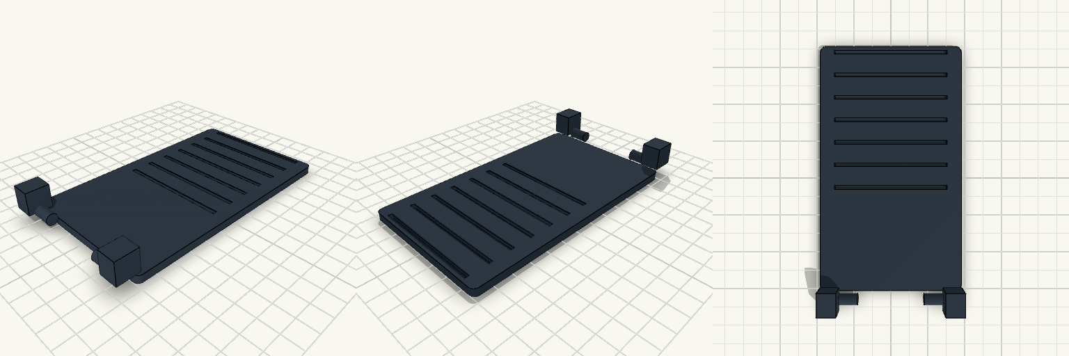
A rugged, fully printable foldable phone stand. It is printed in three flat pieces that snap together securely, allowing it to fold completely flat for travel. Features Adjustable Angles: Features 7 resting notches on the base plate to precisely control the screen angle. Snap-Fit Hinges: Uses C-clip snap joints that grip firmly onto 6mm pins without requiring any extra hardware. Travel-Ready: Folds down to a flat profile when not in use. Print Instructions Print flat on the bed as oriented. Standard PLA or PETG works perfectly. Ensure good bed adhesion for the flat plates. The snap-fit hinges are designed with a 0.4mm clearance — they will require a firm push to snap into place during assembly, but will hold tight thereafter.
ESP32 Enclosure with 1.3 Inch OLED Lid
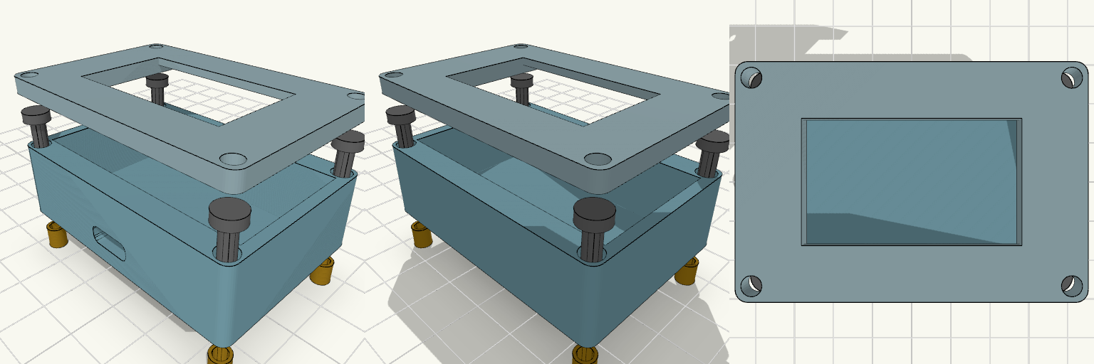
Two-piece enclosure for a 30-pin ESP32-WROOM-32 DevKit V1 with a 1.3 inch SH1106 OLED mounted in the lid. Shown exploded with heat inserts and M3 screws aligned to the corner holes. The lid has a 35.5 x 34.5 mm recess on the underside that holds the OLED PCB, and a 35.5 x 20.5 mm window through the front panel for the visible display area. ESP32 pocket: 52 x 28 mm, 14 mm deep Outer size: about 56.8 x 40.4 mm, 2.4 mm walls Front USB-C slot, 10 x 4 mm Four corner screw holes for M3 screws and heat inserts Front panel thickness behind the window: 1.6 mm Print the lid face-down for a clean front surface.
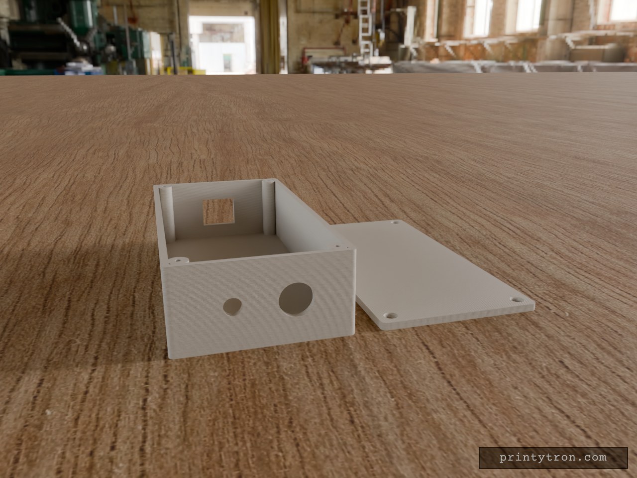
Bulkhead Signal Box with RJ45 and SMA
A compact 130 × 65 × 35 mm enclosure in the spirit of a field-radio interface box: Ethernet in one end, antenna and cable gland out the other. The lid sits flush and is held by four M2.5 × 10 mm countersunk screws threading into corner posts. RJ45 end: 16.5 × 14 mm rectangular opening, centred in width and height. Other end: 6.5 mm hole for a through-mount SMA connector and a 12.5 mm hole for a PG7-style cable gland, spaced evenly across the 65 mm width and centred in height. Walls: 2.5 mm; lid 3 mm, printed flat beside the box. Screws: 2.1 mm pilot holes in the posts for self-tapping M2.5; countersunk clearance holes in the lid.
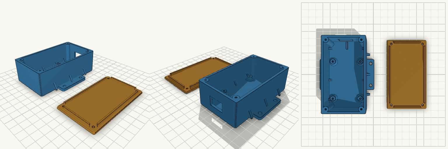
マイコンケース
A two-part enclosure for a 47 × 57 mm STM32F103 board, with a screw-down lid, external mounting flanges and a cable opening at the connector end. The base has 2.5 mm walls, four board bosses at 37 × 50 mm spacing holding the board 5 mm above the floor, and four corner posts for the lid screws. The lid has a locating lip and four clearance holes. Triangular gussets reinforce the flange-to-wall joints and the wall-to-floor joints, and the internal corners are rounded. Total height with lid: 35 mm Connector end extended 20 mm (+Y), with an adjustable cable opening Lid screws: M2.5 self-tapping, 2.2 mm pilot holes in the corner posts Adjustable: hole spacing and offset, boss height and hole size, flange hole size and positions, cable opening, extensions Board hole spacing is approximate and should be checked against the real board