Cable Hub with Sign
Created 1 months ago
Description
Unlabeled cable routing is exactly how you unplug the wrong drive during a transfer. To fix that, this dome now features a snap-fit socket joint holding up a rigid nameplate so it's perfectly clear whose cords belong where.
Sizing and Fit
- Base diameter: 101.6 mm (4 inches)
- Ports: 8 individual routed exits
- Joint: 3mm friction snap-fit
Images
More like this
Explore more in Desk & Tech →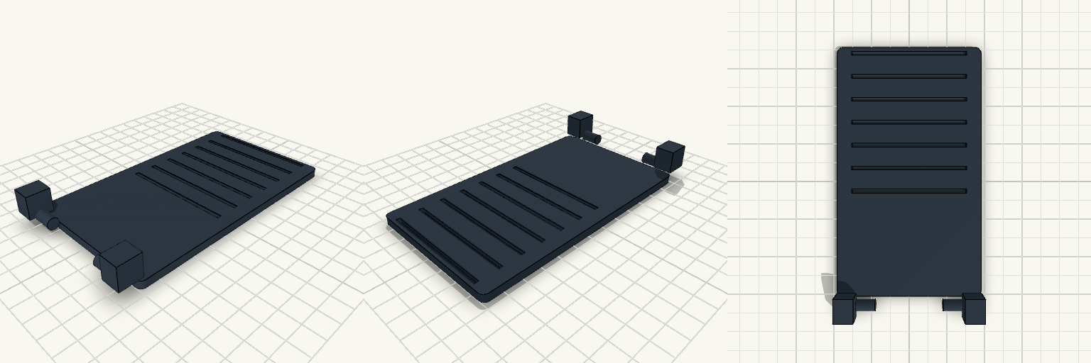
Foldable Snap-Fit Phone Stand
A rugged, fully printable foldable phone stand. It is printed in three flat pieces that snap together securely, allowing it to fold completely flat for travel. Features Adjustable Angles: Features 7 resting notches on the base plate to precisely control the screen angle. Snap-Fit Hinges: Uses C-clip snap joints that grip firmly onto 6mm pins without requiring any extra hardware. Travel-Ready: Folds down to a flat profile when not in use. Print Instructions Print flat on the bed as oriented. Standard PLA or PETG works perfectly. Ensure good bed adhesion for the flat plates. The snap-fit hinges are designed with a 0.4mm clearance — they will require a firm push to snap into place during assembly, but will hold tight thereafter.
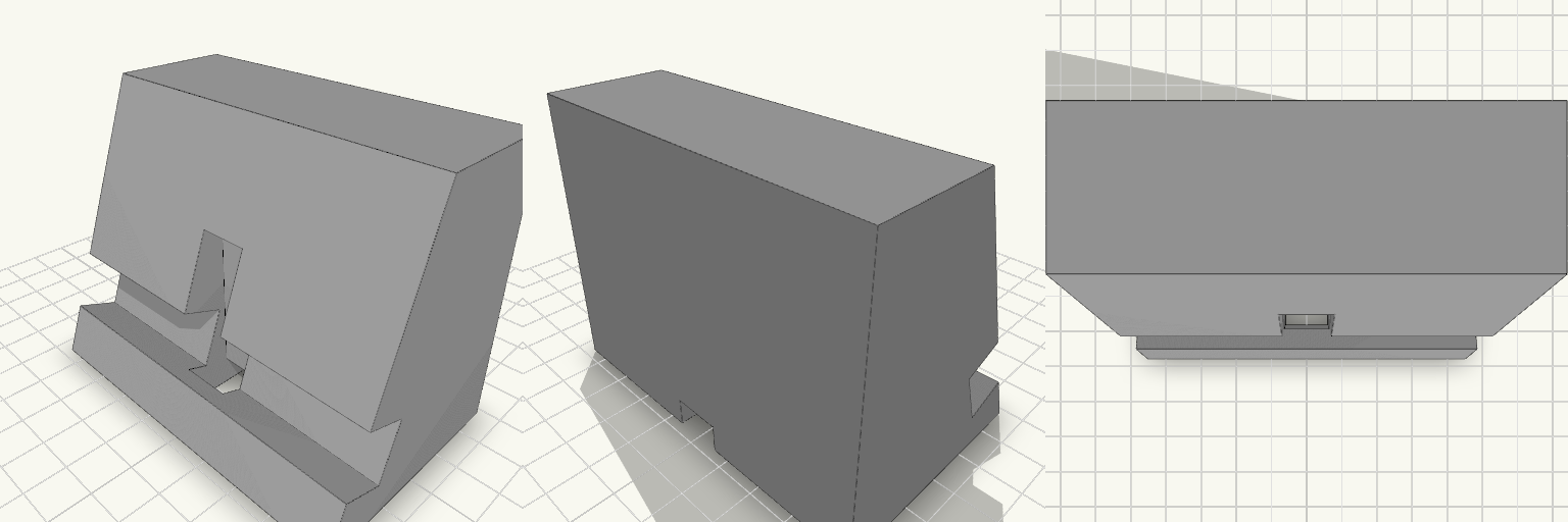
Phone Stand with Cable Channel
A phone stand that holds the phone upright in portrait or landscape, with a cable channel so the charger doesn't pin the phone down or dangle off the edge. Most stands either tip the phone back too far to tap or force the cable to loop around the outside. This one leans the phone at 70° from horizontal and routes the cable up through the stand to the back of the phone. What decides fit and print Lean angle: 70° from horizontal, steep enough to tap the screen and upright enough to watch video. Groove: runs the full 90 mm width, so the phone sits in it in either orientation. It is sized for a phone in a thin case. Cable channel: 12 mm wide, open on the underside of the base. It runs in from the back, then rises through a 12 x 12 mm opening in the groove floor. Overall size: 90 mm wide, about 56 mm deep and 70 mm tall. Printing: the flat base goes down on the bed. The underside channel is a 7 mm-tall tunnel, so print it with bridging on or light supports. No other supports are needed. Material: PLA or PETG both work. Use 3 or more perimeters for a stiffer groove lip.
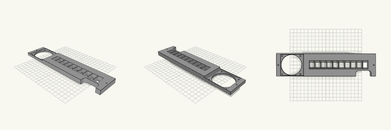
Ten-Port Keystone Panel With Fan
A 270 × 61 mm mounting panel with a 60 mm fan opening on the left and ten snap-in keystone ports on the right. A rounded, squircle-style notch is cut into one long edge near the right end. Remix hooks Notch span: runs from 216.25 mm to 258 mm along X, 15.25 mm deep in Y. Move either end to resize it. Corner radius: both inner corners use a 7 mm radius. Raise it for a softer shape; keep it under about 7.6 mm to stay within the notch depth. Corner material: the notch stops at 258 mm, leaving the right-end 3.5 mm mounting hole (5 mm from the end) fully surrounded. Keystones: 14.5 × 16 mm openings with a 1.8 mm front lip and rear clip relief. Dimensions are provisional, so test one jack before printing all ten. Pairs with: a cable-management bar or a fan grille over the 58 mm vent. It's meant for a particular 12U rack.
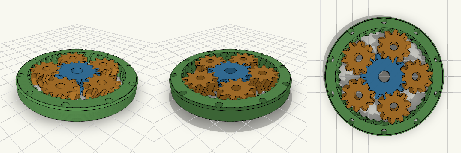
Fidget Spinner Planetario Ø70 mm
Fidget spinner a ingranaggi planetari stampabile in un solo pezzo (print-in-place), diametro esterno 70 mm, con ingranaggio solare centrale, 5 satelliti e anello esterno dentato internamente. L'anello è alleggerito da 10 fori passanti e non ha coperchi, così gli ingranaggi restano visibili. Diametro esterno: 70 mm, spessore 8 mm Modulo 1,5; solare 15 denti, satelliti 10 denti, corona 35 denti Denti elicoidali a spina di pesce (25°) che trattengono i satelliti senza assi Gioco sui denti: 0,25 mm Fori centrali Ø7 mm (solare) e Ø5 mm (satelliti) per alleggerire Stampa piatta, senza supporti; PLA o PETG
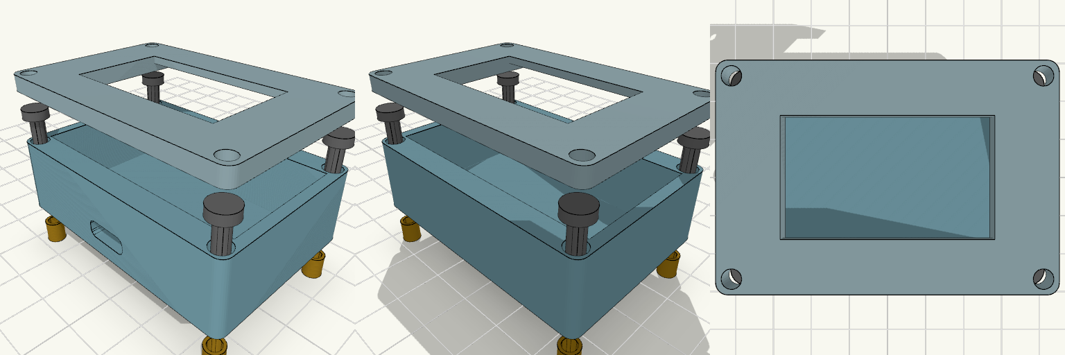
ESP32 Enclosure with 1.3 Inch OLED Lid
Two-piece enclosure for a 30-pin ESP32-WROOM-32 DevKit V1 with a 1.3 inch SH1106 OLED mounted in the lid. Shown exploded with heat inserts and M3 screws aligned to the corner holes. The lid has a 35.5 x 34.5 mm recess on the underside that holds the OLED PCB, and a 35.5 x 20.5 mm window through the front panel for the visible display area. ESP32 pocket: 52 x 28 mm, 14 mm deep Outer size: about 56.8 x 40.4 mm, 2.4 mm walls Front USB-C slot, 10 x 4 mm Four corner screw holes for M3 screws and heat inserts Front panel thickness behind the window: 1.6 mm Print the lid face-down for a clean front surface.
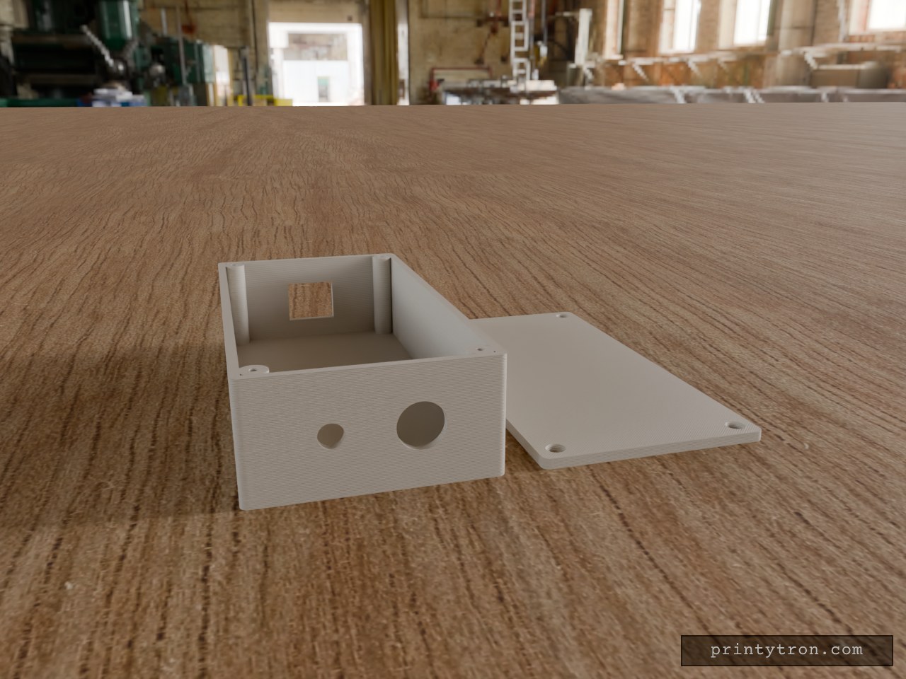
Bulkhead Signal Box with RJ45 and SMA
A compact 130 × 65 × 35 mm enclosure in the spirit of a field-radio interface box: Ethernet in one end, antenna and cable gland out the other. The lid sits flush and is held by four M2.5 × 10 mm countersunk screws threading into corner posts. RJ45 end: 16.5 × 14 mm rectangular opening, centred in width and height. Other end: 6.5 mm hole for a through-mount SMA connector and a 12.5 mm hole for a PG7-style cable gland, spaced evenly across the 65 mm width and centred in height. Walls: 2.5 mm; lid 3 mm, printed flat beside the box. Screws: 2.1 mm pilot holes in the posts for self-tapping M2.5; countersunk clearance holes in the lid.