Mister Box Holder with Open Front
Created today
Description
A wall-mounted cradle for a 2.25" x 4.75" x 2" mister box, sized with extra width clearance and a little extra depth so the box slots in easily but can't tip forward out of it.
The front is open below a solid top rim so the buttons stay reachable, and a low lip along the bottom front edge holds the box in. Two identical ears on the back face carry countersunk screw holes for mounting to the side of furniture.
- Full 4.75" (120.65 mm) wall height
- 10 mm width gap, 3 mm depth gap
- Cord notch in the left rim only, 15 mm wide, centered 1.5" from the inside back wall, open at the top
- Window cutouts on the sides to save filament
- Two back ears with countersunk screw holes
Images
More like this
Explore more in Storage & Organization →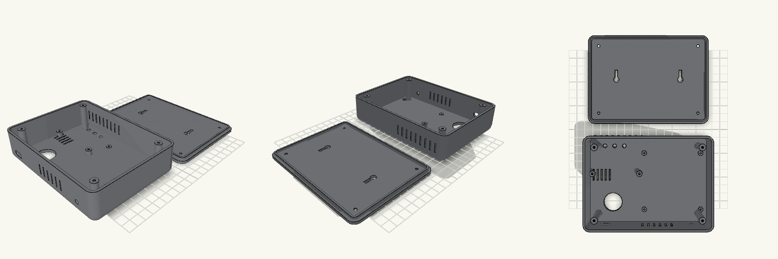
Caregiver Check Station Enclosure, Gray and Red
A caregiver check-in box with no obvious place to tap, and a back panel that fights you at every repair. This enclosure puts a large red TAP HERE panel on the front and a screw-on back cover behind it, so the electronics come out without disturbing the front. Size: 150 × 110 × 36 mm body, with a 3 mm back cover. NFC panel: 64 × 64 × 2 mm red panel, replaceable, behind a 1.5 mm lip. It is held by a separate holder with four M2.5 screws. Back cover: four M3 × 12 screws into body posts, with a 0.3 mm clearance skirt. Two keyhole slots handle wall mounting. Openings: PIR window 23 mm, three 5 mm LED holes (green, yellow, red), BME280 air slots, 12 × 6.5 mm USB-C slot, 5 mm reed-switch cable hole, and top and bottom vent slots. Printing: body and panel face-down, cover outside-down. PLA, no supports, 3 walls, about 15% infill. Not final: every board position is a placeholder. Measure the ESP32, PN532, PIR and BME280 before fixing the internal layout.
Screw-Through Dowel Shelf Bracket
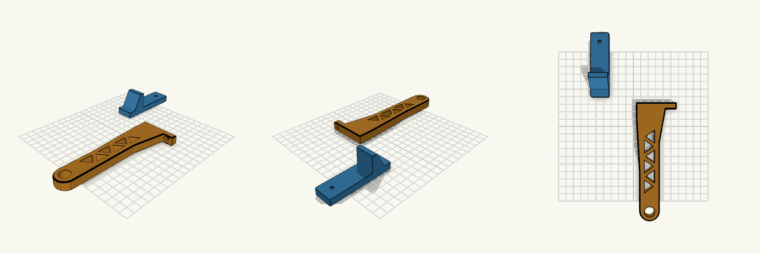
A two-part wall bracket for holding a 13 mm wooden dowel, intended as a filament spool shelf. A narrow wall plate carries a ledge that takes the vertical load, and a separate flat-printed arm rests on that ledge. One screw passes through the arm's back flange and the wall plate into the wall, locking the two parts together. The screw head sits in a recess in the arm. Wall plate: 24 mm wide, 84 mm tall, with a ribbed ledge under the arm Arm: 12 mm thick, printed on its side with no supports Dowel hole: 13.6 mm, 150 mm out from the wall plate Fixing: one screw near the top, shared by both parts Print two sets for a pair of brackets
Two-Piece Gridfinity Caliper Box
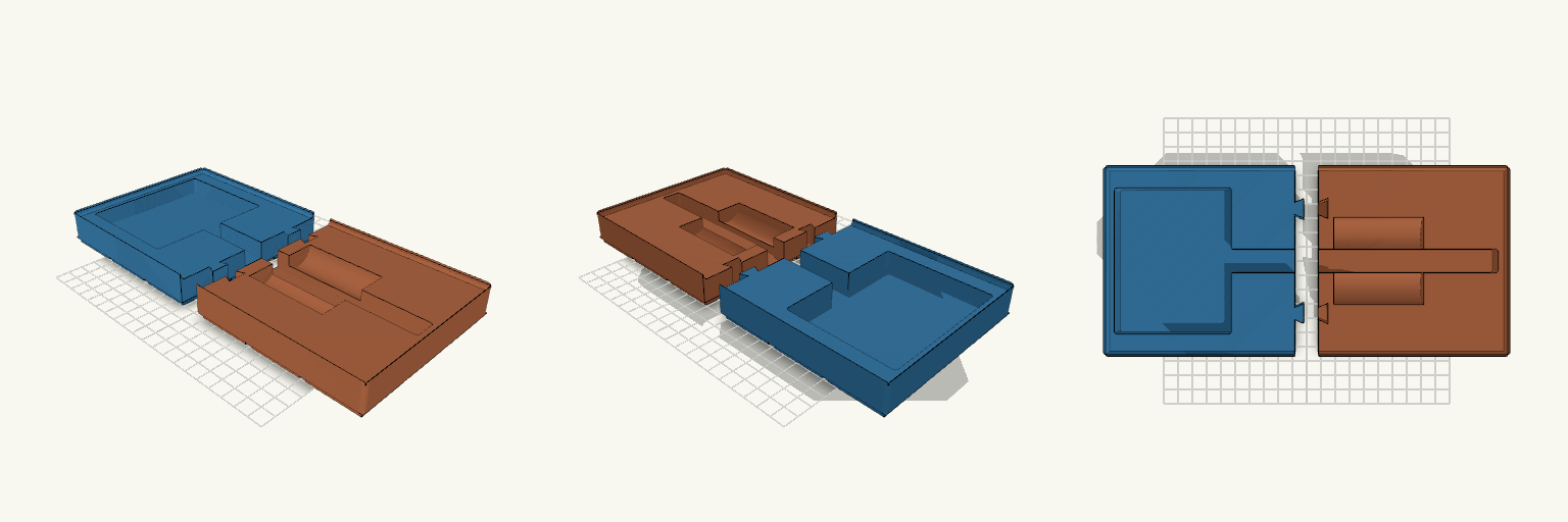
A 6 x 3 unit Gridfinity caliper box split at the middle into two halves, each about 126 x 126 x 25.4 mm, so each fits a 150 mm print bed. Two dovetail keys join the halves. The stepped pocket holds a 9.25 in caliper: a 15.9 mm body slot and a 78 x 97.5 mm head recess, both 12.7 mm deep. The stacking lip and finger scoops are kept. Remix hooks Split position: the cut is at X = 0, on a Gridfinity cell boundary. Moving it in whole 42 mm steps keeps the cells intact. Dovetail size: 8 mm at the root, 13 mm at the tip, 16 mm tall, at Y = ±35. The socket has 0.25 mm clearance. Loosen or tighten it to suit your printer. Joint type: swap the dovetails for round pins or add glue grooves. Pairs with: other Gridfinity bins on a 42 mm baseplate.
Tabletop Wildlife Alert, 100 mm Diamond Sign
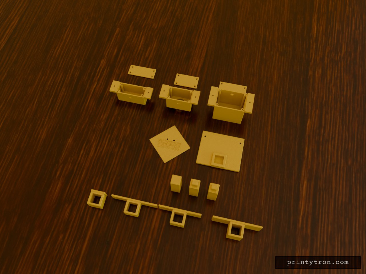
Modular tabletop wildlife-warning prototype printed as separate parts that bolt together: base, three pole sections, four brackets, electronics enclosure with lid, PIR sensor housing with rain hood and lid, amber light housing with lid, and a diamond sign reading WILDLIFE CROSSING with no graphic. The stack runs bottom to top: electronics enclosure, PIR sensor facing forward, two amber LED openings, then the sign. Each housing screws to its own bracket, and each bracket clamps onto the pole with one cross-screw. Dimensions (mm, outside) Electronics enclosure: 70 × 60 × 50, interior about 65 × 57 × 45, with lid PIR housing: 60 × 40 × 35, 23 mm lens opening, rain hood, with lid Light housing: 70 × 35 × 30, two 8 mm LED openings, with lid Sign: diamond 100 point to point, 3 mm thick Base: 100 × 84 × 6 Pole: three sections, 20 × 20 × 58 Overall height: about 224 To confirm before printing Controller board size (a full Uno will not fit the interior) PIR lens diameter and LED diameter (23 mm and 8 mm are placeholders) Printer build area Electronics are untested
Caixa 120x120x50 mm Estação Meteorológica
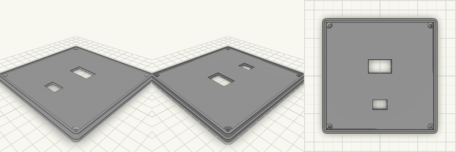
Caixa quadrada de 120 × 120 × 50 mm com paredes de 2 mm e tampa separada, fixada por quatro parafusos M3 nos cantos. Possui abertura para display, chave gangorra, entrada USB-C e fendas de ventilação, além de duas fendas para alça na parte superior da lateral. Parafusos: 4 colunas de canto, furo de 2,8 mm na base e 3,4 mm com escareado na tampa Display: abertura de 24,4 × 14,4 mm na tampa Chave gangorra: abertura de 15,3 × 10,3 mm na tampa USB-C: abertura de 9 × 4 mm na lateral +X Alça: duas fendas de 16 × 4 mm no alto da parede +Y, a 30 mm do centro para cada lado Ventilação: fendas nas laterais, longe das colunas, com fendas extras na região dos sensores Protoboard: dois trilhos baixos no fundo como guia provisório Impressão: base e tampa separadas, sem suportes necessários
Drawer Sleeve Box With Mounting Pad
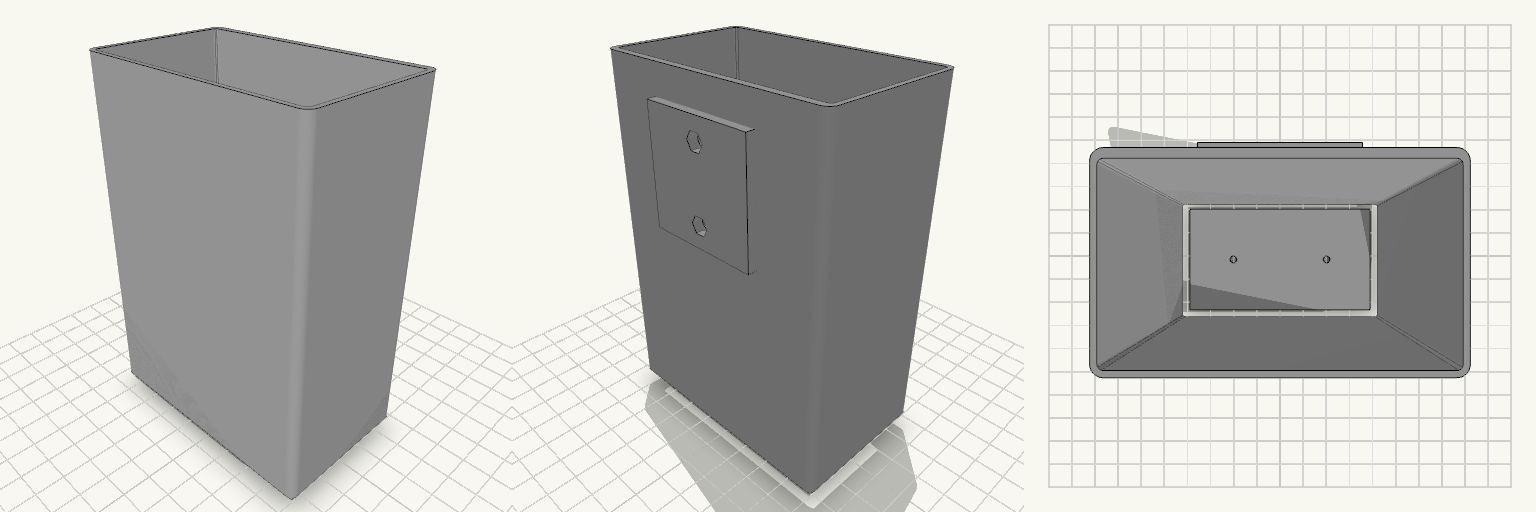
Open-top rectangular sleeve, 86 x 52 x 127 mm, for a sliding drawer. Smooth interior, 1.6 mm floor, sides and front, 2.4 mm back wall. A raised 40 x 40 x 3 mm pad on the back carries two M3 nut traps. Remix hooks Pad position: top edge sits 10 mm below the rim; pad is centered in X. Move or resize freely. Nut traps: 5.7 mm hex, 2.5 mm deep, 25 mm apart, with 3.4 mm blind holes behind them. Blind holes stop 0.8 mm short of the inside; thicken the back wall to go deeper. Edges: 3 mm vertical rounding, 6 mm 45° bottom chamfer (prints without supports). Drains: two 3 mm holes at X = ±20 mm. Pairs with a matching drawer 3 to 4 mm smaller in each direction.