3D-printable workshop tools & shop upgrades
Drill guides, tool racks, sanding blocks, dust-collection adapters — functional shop gear with real dimensions, ready to print. Browse what makers built, or describe the exact tool you need and Printy makes it.
Need one that fits your exact measurements? Start building →
Newest
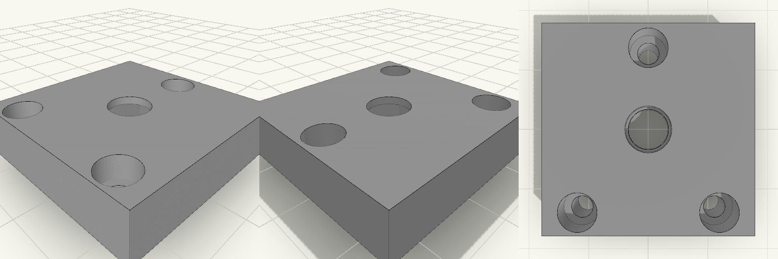
30x30x8mm Interposer Plate, 1/4-20 Nut Pocket
Square-edged 30x30x8 mm interposer plate with a central 6.6 mm hole for a 1/4-20 stud. A hex pocket for a 1/4-20 nut is enclosed inside the plate and is designed for a mid-print pause: the nut is inserted when the print reaches the top of the pocket, and the remaining layers bridge over it. Plate: 30 x 30 x 8 mm, square edges Center hole: 6.6 mm through, for a 1/4-20 stud Nut pocket: 13.2 mm across corners (about 11.4 mm across flats), 5.8 mm deep, from Z 1.0 to 6.8 mm Pause height: Z = 6.8 mm, then resume to print a 1.2 mm cover Screw holes: three 3.3 mm holes with 5.6 mm counterbores from the top face, 3.5 mm deep Triangle pattern: apex 3.5 mm from the back edge, two front holes 20 mm apart Nut size assumed: standard 7/16 in across flats, 7/32 in thick
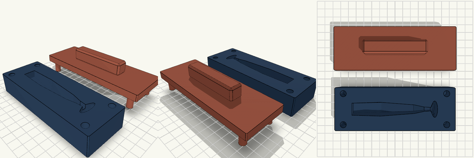
Gießform Köderfisch
Two-piece open-pour mold for a 100 mm soft plastic shad, with a press-stamp that forms a serrated channel in the first layers. The tail ends in a diving paddle that is cut off flat and straight at the rear, like a classic paddle-tail lure. The nose is extended at the front so the bait keeps its 100 mm overall length. Main mold base with deep shad cavity and alignment holes Press-stamp with handle, guide pins and irregular pointed teeth Flat-cut paddle tail with a thick tail root 0.4 mm clearance per side between pins and holes
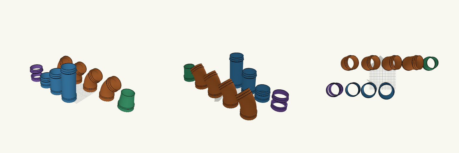
EGO GutterJet — Elliptical Leaf Blower Extension
GutterJet is a modular gutter-clearing extension for an EGO leaf blower, built around a single elliptical adapter that slips over the blower tube and transitions into a round, swiveling system. Only the piece that meets the blower stays elliptical; from there everything is circular, so the bends can be rotated to aim the outlet and the whole run can turn without fighting an oval joint. Every round joint indexes every 15°, letting you lock the U-turn or sweep the outlet to a set angle. The set prints as separate pieces that push together and pull apart with a firm tug, and a tapered reducer nozzle narrows the end of the U-turn for a focused blast. What's included Elliptical adapter: a 30 mm elliptical socket, a 40 mm transition from ellipse to circle, and a 30 mm round spigot with an indexing collar. Three straight tubes: 80, 160 and 240 mm, each with a socket on one end and a beaded spigot on the other. Four identical 45° bends that connect into a 180° U-turn with a 120 mm centreline radius. Reducer nozzle: a 30 mm socket that fits the U-tube spigot, a 60 mm taper, and a 20 mm-long straight nozzle with a 76 mm bore (about 4,536 mm² of flow area). Fit and joints The adapter's socket measures 94.4 × 89.4 mm inside, leaving 0.3 mm clearance over a blower tube of 88.5 × 83.5 mm inside diameter and 2.8 mm wall. Round joints pair a 94 mm spigot (89.2 mm bore) with a 94.6 mm socket. Each spigot carries a 0.9 mm bead ring 15 mm back from its tip; each socket has a matching groove 15 mm in from its mouth. The bead has 45° flanks and the groove has matching 45° faces, so the joint eases in and pulls apart cleanly. A 3 mm collar on each spigot carries 24 shallow teeth on its top face, with matching notches in the socket mouth. The joints click every 15°, including at the adapter, straights and bends. The teeth are 1.2 mm tall with a gentle slope for a soft click. The spigot tip stops just short of the inside shoulder, so the collar and socket mouth are the faces that seat against each other. Walls are 2.4 mm throughout, and the bore is slightly larger than the blower's, so airflow is not restricted. The bead ring is the wear point after many snaps. Print notes Print each piece standing on its socket end. The 240 mm tube fits a 260 mm Z build height; the bend pieces are about 170 mm tall. The layout is for preview, not arranged for one plate — print as many straight tubes as needed. For repeated snapping, print the bead rings at 100% infill or slow the outer wall in those areas. The collar on each bend's tilted outlet is a 45° overhang; watch that face when printing. The set has not been fit-tested; check the adapter socket on the blower tube before printing a full set.
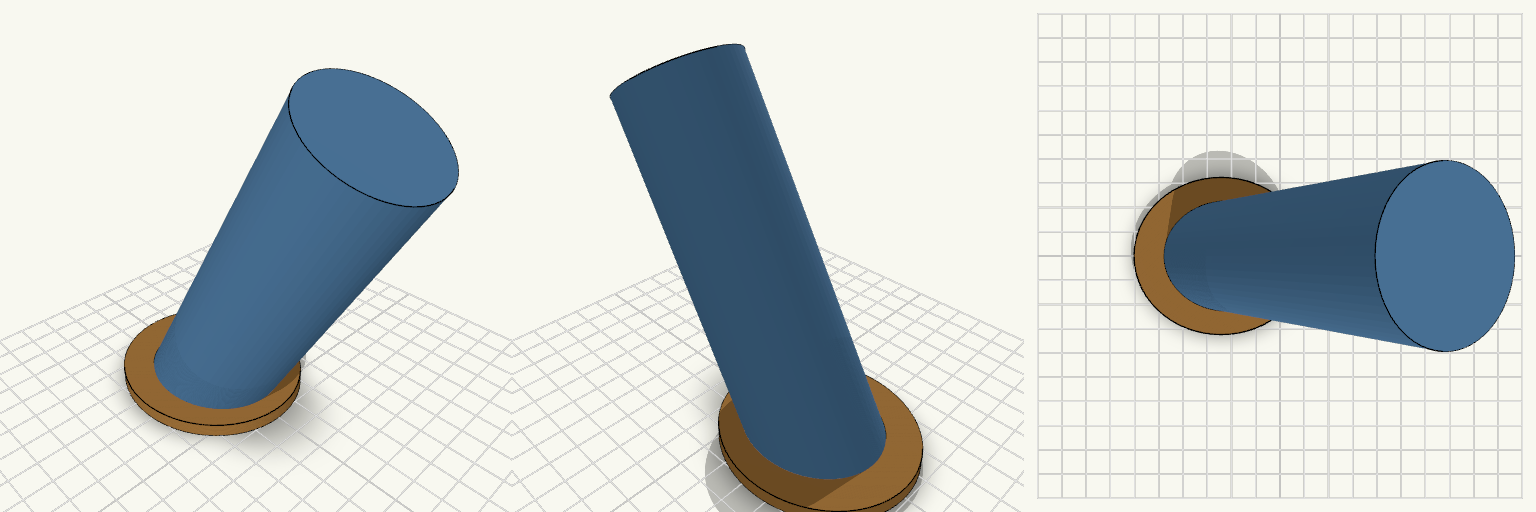
30° Tilted 1.75 in Cylinder With Base
A 1.75 in diameter cylinder leaning 30° from vertical, mounted on a flat base plate. The upper side of the cylinder measures 4.5 in from the base to the top end. Cylinder: 1.75 in (44.45 mm) diameter, 30° from vertical, 4.5 in along the top side Base: 0.18 in (4.57 mm) thick, extends 0.375 in beyond the cylinder footprint on all sides Flat underside, prints without supports on the base; the lean is unsupported on the underside of the cylinder, so a brim or supports may help One continuous solid
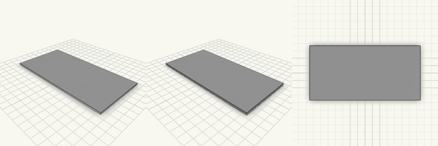
cache moteur araignee
Une plaque plane rectangulaire de 148 × 73 mm pour 2 mm d'épaisseur, posée à plat sur le plateau. Les arêtes sont vives et les faces sont lisses : c'est une base neutre, faite pour être percée, collée, vissée ou redessinée selon le besoin. Elle s'imprime sans support, quelle que soit l'orientation, et sert aussi bien de panneau de fond que de gabarit, de cale ou de renfort. Pistes pour une version à toi Épaisseur (2 mm) : c'est le paramètre le plus utile à faire varier. En dessous, la plaque devient souple et se déforme ; au-dessus de 3 mm, elle devient rigide mais consomme vite de la matière. Garde 2 mm si tu veux une plaque qui se découpe aux ciseaux après impression. Empreinte (148 × 73 mm) : les deux cotes sont libres. La diagonale vaut environ 165 mm, donc la plaque tient dans la plupart des plateaux sans dépasser. Arêtes vives : un congé de 1 à 3 mm sur les quatre coins change complètement le rendu et évite les angles qui s'ébrèchent. Un chanfrein sur le pourtour donne un bord plus doux au toucher. Perçages et découpes : trous de fixation aux quatre coins, rainure centrale, fenêtre traversante — tout se rajoute sans toucher au contour. Ce avec quoi elle s'associe Une plaque comme celle-ci se superpose : deux exemplaires collés font une cale de 4 mm, un exemplaire vissé sur un caisson fait un fond ou une porte, et un exemplaire percé devient un gabarit de perçage. Si tu la destines à un objet précis, indique les cotes de cet objet plutôt que de repartir de zéro : c'est la seule mesure qui compte vraiment.
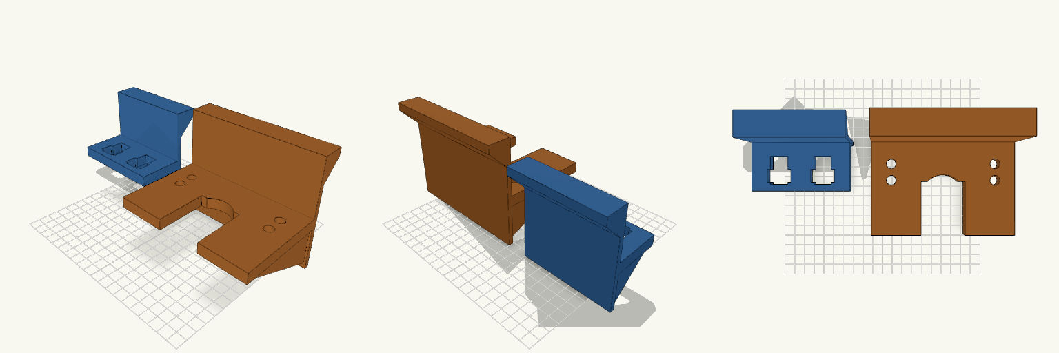
French Cleat Pliers and Drill Holders
A pair of tool holders that hang on a 45° french cleat wall: a pliers rack and a cordless drill holder. Each has a matching 45° lip on the back, sized for an 18 mm ply cleat with 0.5 mm of clearance, so it drops on and stays put under its own weight. Built for a bare garage wall where the tools currently live in a bucket. Pliers holder: 90 mm wide, 95 mm tall, with a 10 mm shelf that projects 45 mm. Two handle slots sit at 25 mm and 65 mm across and taper slightly open toward the back. Drill holder: 130 mm wide, 105 mm tall, with a 10 mm shelf that projects 85 mm. A 40 mm round chuck opening is open to the front, and four 9 mm bit holes sit near the side edges. Remix hooks Cleat size: the cleat thickness (18 mm) and clearance (0.5 mm) drive the lip. Change them to match 12 mm or 19 mm stock. Tighten the clearance only after a test print. Slot count and spacing: add more pliers slots by widening the holder and repeating the slot positions. Narrow or widen each slot to suit your handle thickness. Chuck opening: the 40 mm diameter suits a typical cordless drill chuck. Adjust it for larger drivers or impact guns. Drill extras: the bit holes are 9 mm. Resize them for hex bits or drill bits, or replace them with a battery cradle. Shelf strength: the shelf is 10 mm thick with 4 mm gussets. Thicken it for heavier tools. Pairs well with More cleat-mounted holders cut to the same lip profile. A length of 45° ply cleat screwed into studs, with the holders spaced about 20 mm apart (the pliers holder is 90 mm wide and the drill holder is 130 mm wide). Print each holder on its back, and test the cleat fit on a short piece before committing to a full print.
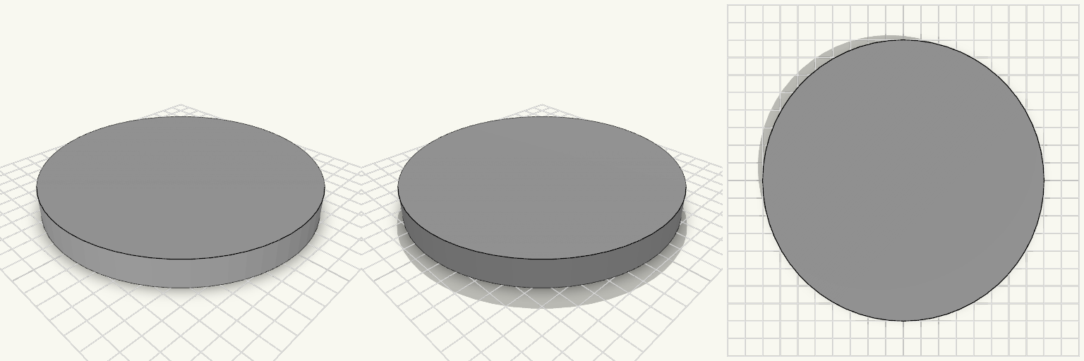
Korong
Egy teljesen sima korong: 80 mm átmérő, 10 mm magas, felirat, furat és bemélyedés nélkül. Szándékosan üraes — ez egy kiindulópont, amiből bármi kerek és lapos válhat: alátét, távtartó, sapka, fedél vagy egy nagyobb darab talpa. Mit érdemes rajta módosítani Átmérő: a 80 mm a stabil alap; ha kisebb korong kell, ezt állítsd át elsőként, a magasságot hagyhatod. Magasság: a 10 mm biztonságosan nyomtatható; 4–6 mm-re csökkentve lapos alátét lesz belőle, 20 mm fölé növelve inkább henger, mint korong. Él: a mostani él éles — 1–2 mm-es lekerekítés kényelmesebb fogást ad, és kevésbé hajlamos a peremfelpúposodásra. Középfurat: egy 4–8 mm-es átmenő furat távtartóvá vagy csavarhüvellyé alakítja, és felhasználás előtt nem kell átfúrni. Felület: a sima tető kínálja magát gravírozott felirathoz, logóhoz vagy mintázathoz; ehhez nem kell új geometria, csak egy sekély bevonat. Amivel jól működik Több példány egymásra rakva pontos vastagságot ad, így kiegyenlítéshez és rések kitöltéséhez is használható. Egy csavarral vagy csappal a közepén távtartóból rögzítőelem lesz, két korong közé szorítva pedig bármilyen vékony lapot merevíteni lehet. Nyomtatás: 80 × 80 × 10 mm, laposan fekszik a tárgyasztalon, támasz nélkül nyomtatható. Ragasztás vagy összeszerelés nem kell hozzá, egy darabból készül.
Kostka 15 mm do sprawdzania skali wydruku
Kostka 15 mm to sześcian 15 × 15 × 15 mm bez otworów, faz i wystających elementów — leży płasko na płycie i nie wymaga żadnego ustawiania podpór. Drukuje się w jednym kawałku, więc po zdjęciu z płyty od razu wiadomo, czy wymiar w przekroju i w wysokości się zgadza. Co decyduje o dopasowaniu Wymiar: 15 × 15 × 15 mm — sprawdzaj wszystkie trzy osie, nie tylko podstawę. Ściany: pełny sześcian, bez wnęk i otworów, więc nic się w środku nie zapada. Podpory: niepotrzebne, cała bryła stoi na płycie. Montaż: brak, jeden element. Przy tak małym elemencie warto trzymać się skali 1:1 — przeskalowanie w programie przygotowującym wydruk zmienia wymiar, który kostka ma potwierdzać.
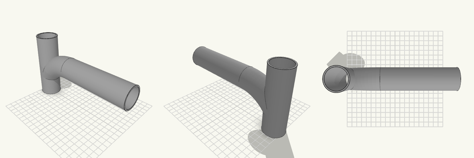
Sweep — Y-Absaugrohr mit 90°-Bogen
Sweep ist ein Y-förmiges Absaugrohr mit geradem Hauptrohr und einem seitlichen Abzweig, der in einem weichen Bogen auf 90° übergeht. Der Bogen folgt einem Mittellinienradius von 75 mm und sorgt für geringe Turbulenzen. Dimensionen Außendurchmesser: 40 mm Innendurchmesser: 35,5 mm (Wandstärke ca. 2,25 mm) Hauptrohr: 120 mm, gerade und durchgehend Abzweig: Start bei 35° zur Achse, Bogen von 55° bis 90°, gerader Endstutzen von 30 mm Features Konstanter runder Innenquerschnitt Keine Überstände auf der Gegenseite des Hauptrohrs
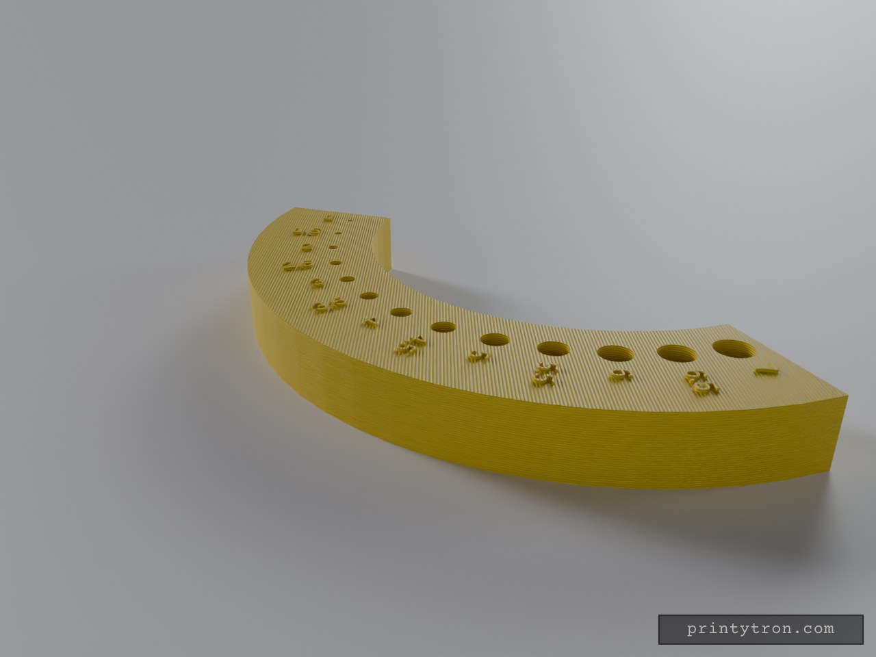
Drill Bit Index for 1–6.5 mm Bits
A drill bit index that stops you digging through a drawer to find which bit is a 4 mm. Thirteen sized holes fan out along an arc, each with its size embossed beside it, so you can read the number and pull the bit without guessing. Each hole is cut 0.3 mm over the nominal bit diameter. That is enough for the bit to drop in and lift out, and tight enough that it does not rattle around. Numbers that decide fit and print Bits: 13 holes, 1 mm to 6.5 mm in 0.5 mm steps Clearance: +0.3 mm on every hole (a 1 mm bit gets a 1.3 mm hole) Hole depth: 12 mm Layout: 60 mm radius arc, 10° between holes, fanned like piano keys Overall size: about 144 mm wide, 58 mm deep, 14 mm thick Labels: raised 0.6 mm, with the left-half labels flipped to read upright Printing Print flat with the labels facing up. No supports are needed. Use a 0.2 mm layer height or finer so the 1.3 mm hole stays open. Ream the smallest holes with the bit itself if your printer shrinks them. The labels are a separate colour region, so they suit a filament swap at layer 14 mm.
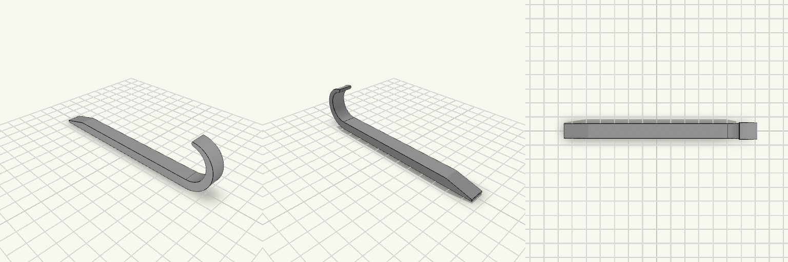
Mini Pry Bar for Stuck Edges and Gaps
A mini pry bar for the gap that is too tight for a fingernail and too shallow for a real crowbar — nothing gets under the edge, so the lid stays shut, the panel stays seated, the trim stays put. It is a flat 4.5 in bar, 2/5 in wide, with a chisel-bevel straight end to start the lift and a 175° claw hook at the other end to catch and hold what you have opened. What it does at each end Chisel-bevel straight end: taps into a seam and starts the gap. 175° hook: wraps the edge you have lifted so it does not drop back. Slanted claw tip: cut at a 35° slant like a crowbar claw, so it bites instead of skating off. Full-width hook: the hook stays 2/5 in (10.16 mm) wide from the handle to the tip, so it catches the full edge instead of narrowing away. Sizes that decide fit Bar length: 4.5 in (114.3 mm), with the hook adding to the overall footprint Overall width at the handle: 2/5 in (10.16 mm) Bar thickness: 6 mm at the handle, thinning to about 2 mm at the hook tip Hook curl: 175° around a 14 mm centerline radius — check this against the edge you want it to wrap Printed footprint: about 130.5 × 10.2 × 31.9 mm, lying flat Printing One piece, straight off the plate — the bar and the curve share solid material at the joint, so there is no slip fit, no glue, no assembly. Lay it flat as it comes and print; the flat bar and the curl sit on the plate without supports. Check the curl radius and the 2/5 in width before you start; those two decide whether the hook wraps your edge or rattles around it. Look over the joint between the bar and the hook in the preview first, since that is where the two shapes meet.
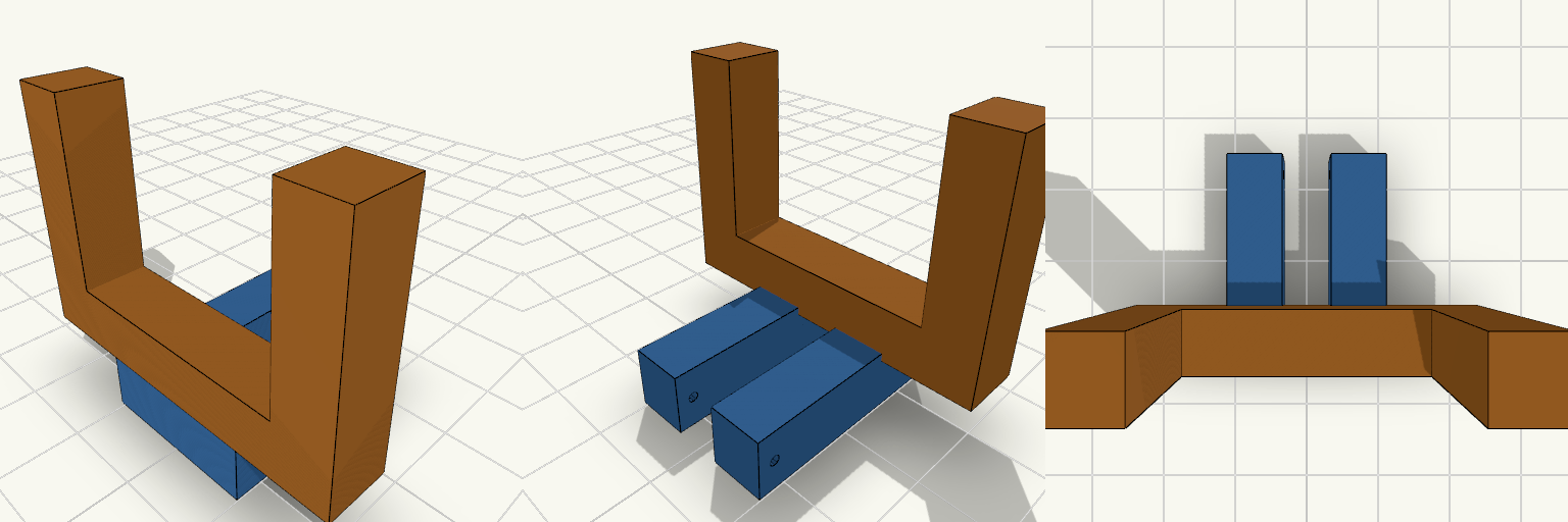
prototype adapt traxx
Une pièce à deux U à 90° cale et espace un montage sans que l’écart glisse à la mauvaise distance : le petit U reste à plat, ouvert vers l’arrière, et le grand U se dresse à la verticale sur sa base. Les deux U sont réunis en une seule pièce, le grand U étant enfoncé de 1 mm dans le petit à la jonction. Un trou de 1,3 mm traverse les deux pattes du petit U de part en part, à mi-hauteur, à 1,5 mm du bord de l’extrémité ouverte. Cotes qui décident du montage : Petit U (à plat) : écart intérieur 6,2 mm, longueur 27,2 mm, encombrement 20,2 × 27,2 mm, hauteur 7,9 mm. Grand U (debout) : intérieur 29,4 × 22,8 mm, encombrement 43,4 × 29,8 mm, épaisseur 7,9 mm. Les deux : branches et fond à angle droit, même épaisseur de 7,9 mm. Alignement : le grand U est centré sur le petit et dépasse d’environ 11,6 mm de chaque côté. Jonction : grand U enfoncé de 1 mm dans le petit U ; une seule pièce, sans congé ni renfort ajouté. Trou du petit U : Ø 1,3 mm traversant les deux pattes, à 1,5 mm du bord ouvert, à mi-hauteur. La pièce s’imprime d’un seul tenant. Le petit U tient l’écart de 6,2 mm sur 27,2 mm de long ; le grand U offre un logement intérieur de 29,4 × 22,8 mm, branches vers le haut. Garder l’échelle 1:1 à l’impression : ce sont les cotes intérieures qui décident si la pièce se loge ou force.
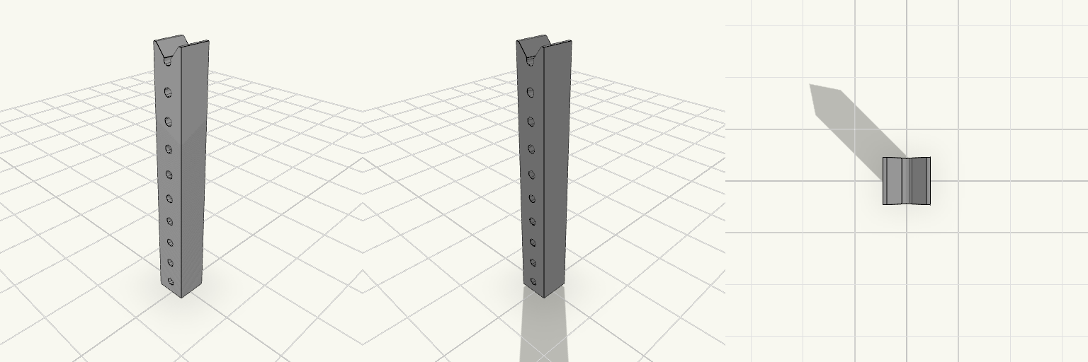
chandelle ajustable
Ce à quoi ça sert Une barre de section carrée 4,8 × 4,8 mm et de 40 mm de haut, percée de dix trous de 1,3 mm répartis régulièrement du haut jusqu'au bas. Les trous traversent la barre de part en part : on peut y passer un fil, une tige fine, une aiguille ou une petite vis autotaraudeuse. La barre reste compacte et se glisse facilement dans une poche d'outils ou un tiroir. Le sommet reçoit une rainure en V de 2,5 mm de profondeur, ouverte sur 4 mm en haut et traversante dans le même sens que les trous. Elle sert de guide ou de berceau pour une arête, un fil tendu ou une tige posée en travers du haut de la barre. Dimensions Largeur : 4,8 mm Profondeur : 4,8 mm Hauteur : 40 mm Section : 4,8 × 4,8 mm Trous : 10 × Ø 1,3 mm, traversants, espacés régulièrement sur toute la hauteur Rainure en V : 2,5 mm de profondeur, 4 mm d'ouverture, traversante Notes d'impression La pièce est fine et allongée : une buse de 0,4 mm suffit, mais les trous de 1,3 mm demandent une bonne calibration pour rester débouchants. Imprimer sans supports ; posée debout, la rainure en V s'ouvre vers le haut. Vérifier le diamètre réel des trous avant d'y engager une tige ou une vis. La rainure laisse le trou le plus haut entier : les dix trous restent utilisables. Idées de remix Réduire encore la profondeur du V, ou l'ouvrir davantage, selon ce que le sommet doit accueillir. Tourner la rainure d'un quart de tour pour qu'elle croise les trous au lieu de les suivre. Remplacer les dix perçages par un seul canal sur la longueur, ou modifier leur espacement pour un montage précis.
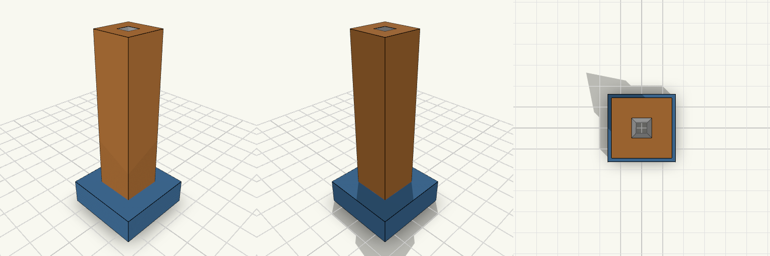
support avec trou
Pilier est une pièce de maintien compacte : une semelle carrée de 30 × 30 mm sur 10 mm d'épaisseur, surmontée d'une colonne centrée de 15 × 15 mm. Un trou carré de 5 mm traverse toute la pièce de haut en bas, semelle comprise, ce qui laisse un logement traversant pour une tige ou un axe carré. La silhouette reste volontairement simple — un socle large et stable, une colonne étroite, un alésage carré — pour que la pièce serve de support vertical ou de module de base à combiner avec d'autres éléments. Dimensions Semelle : 30 × 30 × 10 mm Colonne : 15 × 15 × 60 mm, centrée sur la semelle Hauteur totale : 70 mm Trou carré traversant : 5 × 5 mm, sur toute la hauteur Notes d'impression La pièce s'imprime d'un seul tenant, posée à plat sur sa semelle. Le trou carré est vertical : aucun support n'est nécessaire à l'intérieur du perçage. Une paroi de 5 mm autour du trou sur la colonne garde l'ensemble rigide sans être massif.
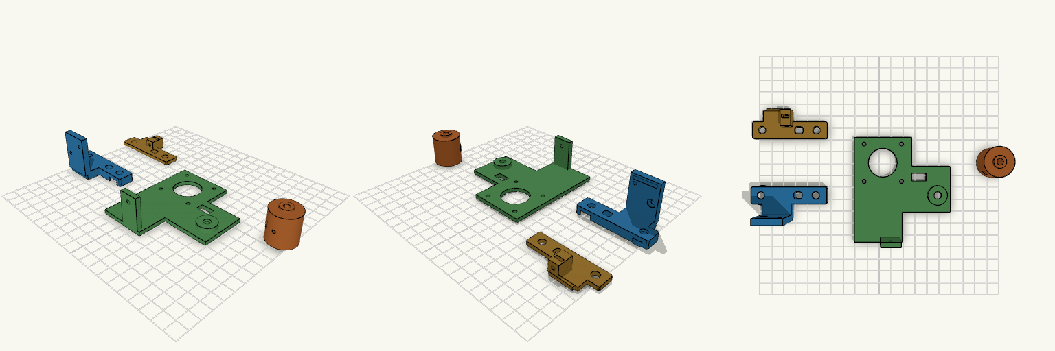
Spring-Loaded Pinch Roller Arm for Wire Feed
A wire feeder fails at the pinch point first: the wire skates sideways or gets crushed under a fixed idler. A spring-loaded pinch roller gives the idler somewhere to move. The pivoting arm carries an M6 bolt for your bearing idler and presses it onto the wire over the drive roller; the pivot and spring sit on +X so the -X side stays clear for the wire guide tube. The printable set is four parts — motor frame, pinch arm, arm cheek and drive roller — with the hardware left out of the print. What prints Motor frame: a trimmed plate, 16.5 mm shorter on the wire-tube end, with square-cut corners so it sits flush. The plate is cut back above the pivot boss and below the IR slot. It carries the 31 mm NEMA 17 hole pattern and 24 mm boss hole, the pivot boss with its M6 nut pocket, the spring bracket, and a 12 mm × 6.5 mm rectangular IR sensor slot on the pivot side. Pinch arm: the main half — pivot end, cheek, posts and raised cross-bridge with an M3 nut trapped in it for spring preload. The cheek is 14 mm tall, the pivot end has about 5.9 mm of plastic beyond the pivot hole, and the idler end stops 8 mm past the idler hole. Each cheek has one rounded 7 × 6 mm lightening window between the pivot recess and the posts, with at least a 4 mm rim around the holes. Its underside carries the groove the other half slots into. Arm cheek: the second half of the arm, held on by one M3 screw through the bridge into a trapped nut in a block on its inner face. It matches the pinch arm’s 14 mm cheek height and lengthened pivot end, and carries the same lightening window. The idler bolt passes through both halves into a trapped M6 nut, with about a 2 mm wall behind the widened pocket. Drive roller: 24 mm diameter, on a 5 mm D-bore through a 10 mm hub. The M3 grub screw has a trapped hex nut that slides in through a slot open to the rim. Print orientation Motor frame: lay it on its motor-side face directly on the bed. The M6 boss and spring bracket point up, and the nut pocket is on the bed face. The 12 mm slot is a vertical cut-through, so the frame prints without supports. Pinch arm: it lies flush on its bed face — the cheek and post are 7 mm thick so the nut boss no longer holds anything in the air. The pivot recess opens onto the bed face as a shallow pocket, not a bridged span. The 17 mm recess is wider than the 14 mm cheek, so it opens through the top and bottom edges; the full-thickness cheek behind it carries the load. The bridge wall is tall, so use 4–5 walls and slow the upper layers. No supports. Arm cheek: lies on its outer face, flat, with no supports. Drive roller: stand it on its end so it comes out round. The nut slot opens to the rim, so it prints without bridging. None of the four parts needs supports. Use 4–5 walls on both arm halves, since the joint is where the load passes; 3 walls and 25–30% infill on the roller, and the plate can go to about 20%. All four can be printed in the same black filament; the viewer colours only separate the parts. Rough total is about 80–115 g in PETG at 3–4 walls, but your slicer’s estimate will be better. The arm joint Tongue: a 2.5 mm wide, 1.8 mm tall rib, 18.9 mm long, on top of the arm cheek’s post. Groove: a 2.9 mm wide, 2 mm deep, 19.5 mm long slot in the underside of the bridge. It is closed at both ends, so the tongue stops the halves sliding sideways or lengthways. Fit: 0.2 mm clearance on each side of the tongue and 0.3 mm at each end, and the tongue stops 0.2 mm short of the groove roof so the post top sits flat against the bridge. Screw: one M3 × 14 down through the bridge into the trapped nut in the cheek block. The block sits outside the bearing’s swing, so the 30 mm roller clears it. The idler and pivot bolts clamp the halves as well. Test-fit the tongue and the nut slot before assembling the full arm. IR sensor slot The motor frame has a 12 mm wide by 6.5 mm tall rectangular slot through the plate on the pivot side, centred on the wire line — the nip between the rollers, about 12 mm above the drive roller’s axis — so a reflective IR proximity module looks across the wire. There is no shelf: the plate is a clean vertical cut-through and the frame sits flat on the bed for printing. The module board has to be held square with a dab of glue or a zip tie. The 6.5 mm height gives a 5 mm LED about 0.75 mm of clearance above and below. The slot is well out from the motor boss hole, so the two don’t meet. Check your module’s board thickness and LED height against the slot before printing. What it fits Idler: the arm carries an M6 × 35 bolt for a 30 mm × 25 mm bearing roller — head and washer on one side, trapped M6 nut in the cheek boss on the other, so the nut cannot spin while you tighten. The cheek gap is 26 mm against a 25 mm roller, so add a thin spacer each side so only the inner race is loaded. Spring: 14 mm long, 7 mm OD, 5 mm ID, between the raised cross-bridge and the frame bracket. The M3 × 22 screw threads into an M3 nut trapped in the 5 mm thick bridge, and turning it sets the preload. Pivot: 6.2 mm hole through the plate and boss, with a 5 mm deep hex pocket for an M6 nut on the back, so the arm is clamped by bolt and nut rather than by the printed boss alone. The arm cheeks were lengthened at the pivot end and made 14 mm tall to leave more material around the pivot hole; the idler end is now shortened and lightened. Clearance: the plate and pivot boss sit back so the arm cheeks clear the plate by about 4 mm and the drive roller hub by about 5.5 mm. That puts the roller further from the motor face — check the motor shaft actually reaches it before bolting anything down. Hardware to have on the bench | Item | Size | |---|---| | Idler bolt | M6 × 35 hex head, with M6 nut and washer | | Roller spacers | thin M6 washers or shims, about 0.5 mm each side | | Pivot bolt | M6 × 45, nut in the back pocket, nyloc nut and washers at the arm end | | Spring screw | M3 × 22 with M3 nut trapped in the bridge | | Arm joint screw | M3 × 14 with M3 nut trapped in the cheek block | | Drive roller grub screw | M3 × 6–8 set screw with M3 nut in the rim slot | | Spring | 7 mm OD, 5 mm ID, 14 mm long compression spring | | Frame screws | 4 × M3 × 8–10 on the 31 mm NEMA 17 pattern | Fit, force and checks before printing Pinch force: the spring sits close to the idler shaft, giving a ratio of spring distance to idler distance from the pivot of about 0.87 — nearly all the spring force reaches the wire. More pinch means a stiffer spring, not a longer screw. Roller gap: the 24 mm drive roller and 30 mm idler are set so their surfaces touch at the nip. There is no gap for the wire until the arm lifts. There is no stop screw, so the arm can close fully with nothing in it; set the preload with a piece of wire in place, or add a stop. Nut pockets: the M6 pockets are 12.2 mm across corners and the M3 pockets are 6.9 mm, with 6.2 mm side slots for the sliding nuts. Your under-5 mm nuts sit fully in the 5 mm deep M6 pockets. Still test-fit a nut before printing the full set. Filament: PETG for the frame and both arm halves, since the NEMA 17 plate runs warm and PLA creeps near it. PETG, ASA or nylon for the drive roller — nylon wears best, and a thin rubber or TPU sleeve adds grip if the wire slips. Before printing: the nut pockets, the tongue-and-groove clearance and the hole clearances are untested on your printer, so print the roller first and test-fit the nut before committing the rest. Keep the four parts in the orientations above, leave the hardware out of the print, and don’t overtighten the joint screw — that is the likelier way to crack the arm.
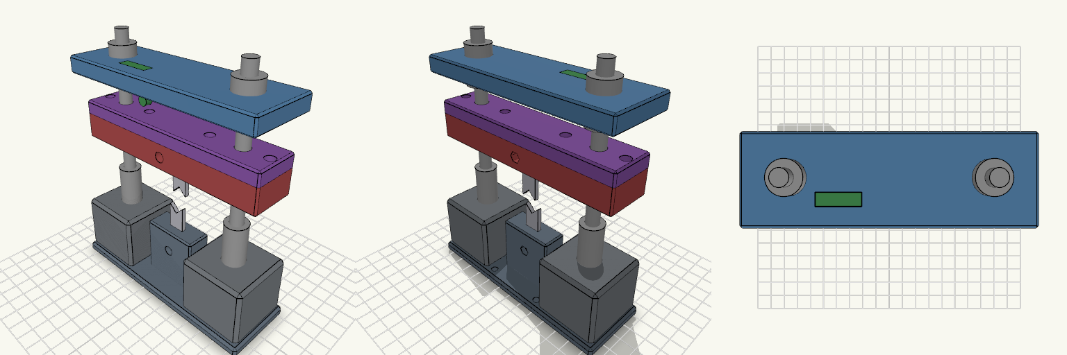
Twin-Screw Guillotine Wire Cutter
A guillotine wire cutter in the spirit of a workshop shear: two V blades pass each other with no face gap, driven by twin 8 mm lead screws on NEMA 17 motors. Design notes Base and bottom blade holder print as one upright piece. Split carriage captures the flanged nuts between two halves. Hex nut traps are 7.0 mm; blade holes sit 4 mm from the held end. Assembled view shows black motors, screws, nuts, blades and limit switch for visualisation only.
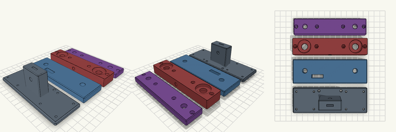
Twin-Screw Guillotine Wire Cutter
A bench guillotine in the spirit of a miniature paper-cutter: two lead screws drive a split carriage so a pair of V blades close on the wire from the sides toward the middle, with a clean cut instead of a pinch. Design notes Top blade nut slides into a hex slot from the back face, so nothing has to be dropped in from the joint. Carriage clamp bolts: M3 x 10 or M3 x 12 both fit, since the bolt holes leave room below the nut. Every part prints flat on the bed with no supports; the horizontal blade-bolt holes are small enough to bridge. Base and blade holder are one piece, with two NEMA 17 motors, a top plate and a split carriage.
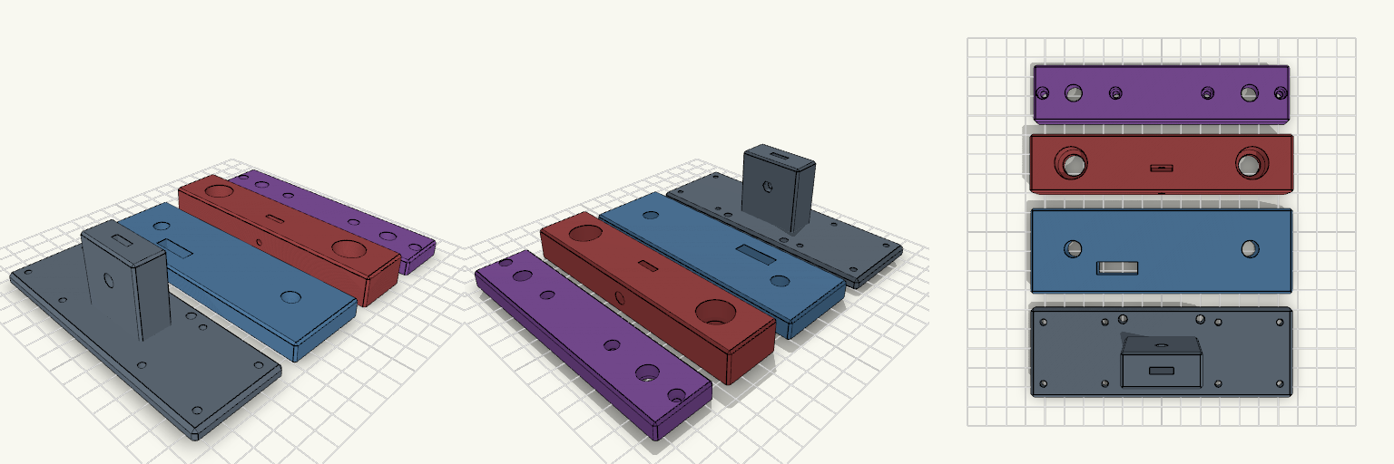
Guillotine Wire Cutter with NEMA 17 Screw Drive
A wire cutter that pinches the wire and spits it back instead of shearing it is the failure this guillotine is built around. Two 8 mm screws, one down each side, move a split carriage whose two V blades pass each other with no face gap, so the cut closes from the sides toward the middle instead of trapping the wire. The base and the bottom blade holder print as one piece, so nothing loosens or pries up under the cutting load, and each flanged nut is captive inside the split carriage, so nothing sticks up into the switch area and the carriage is pulled down as well as lifted. Fit and print numbers Cutting height: the bottom blade's V bottom sits exactly 53 mm above the base underside, set to line up with a feeder. The holder stands 42 mm tall and grips 18 mm of the blade; the blade bolt head is open at the front, so a blade change needs no channel cut into the base. Base and blade holder: one piece, 132 × 45 × 42 mm overall, with a 6 mm base that sits just around the motors. Split carriage: lower half 128 × 28 × 16 mm, upper half 128 × 28 × 8 mm. Four M3 × 10 mm bolts clamp the halves, with the nuts trapped in the lower half. Each flange sits in a 22.8 mm round pocket, 3.5 mm deep, at the joint, and the 2 mm stub rises into a relief in the upper half. No bolts go through the flange holes. Drive: two NEMA 17 motors, 41 × 41 × 37 mm, bolted down with four M3 screws on the standard 31 mm pattern — 3.4 mm clear holes with 6.2 mm counterbores underneath. The two 8 mm screws are 100 mm long, joined to the motor shafts by 25 mm couplers (12.5 mm on the 5 mm shaft, 12.5 mm on the screw). Top plate: 130 × 42 × 10 mm in one piece, with no bearing in it. Each screw passes through a plain 8.6 mm hole, and the plate is sandwiched between two 8 mm clamping shaft collars (about 16 mm OD, with set screws) — one under the plate, one on top. A flat M8 washer on each side cuts friction. The collars clamp anywhere on the screw, so the screw ends can be trimmed; they currently stand about 15 mm above the plate. T8 nuts above and below the plate are the alternative if you would rather not use collars. Blades: each V blade is 10 × 2.5 × 34 mm, standing upright, with a 5 mm deep V notch — 29 mm to the V bottom at the centre — and a 3.3 mm hole centred 3 mm from the held end. The top blade sits 2.5 mm behind the bottom one, one blade thickness, so the faces touch. At the open position the blade tips are 8 mm apart and the V bottoms are 18 mm apart vertically. A 6 mm wire clears only if it sits centred side to side. An M3 bolt enters from the front through the hole into a hex nut trap in the back face of the holder, so a blade can be changed without splitting the carriage. Limit switch: 20 × 6 × 10 mm body with a roller underneath. The body sits in a 20.4 × 6.4 mm slot in the top plate, wires running out the top. The slot sits at X = -22, clear of the screw hole and the collars. The roller hangs below the plate directly over the flat top of the carriage, and the carriage itself trips it after about 8.5 mm of upward travel — no trigger post to print or lose. Tolerances already in the model Blade pockets: 10.6 × 3.1 mm for the 10 × 2.5 mm blade, about 0.3 mm of play per side. Blade bolt holes: 3.6 mm for M3. Flange pockets: 22.8 mm for the 22 mm flange. Barrel holes: 11 mm for the 10.2 mm barrel. Screw holes: 8.6 mm for the 8 mm screw. Fitting the flanged nuts The carriage splits at the flange, so the nut drops in rather than being pushed through anything. Lay the lower half with its joint face up. Drop the nut in barrel first — the barrel goes down through the 11 mm hole until the flange sits in its pocket. The 2 mm stub points up out of the pocket. Set the upper half on top; its relief takes the stub and the flange is clamped between the halves. Fit the four M3 bolts. Print layout The model comes as four parts, each flat on the bed with no supports, in a footprint of about 132 × 167 mm: Base and blade holder in one piece, standing upright. Top plate, flat on its bottom face. Carriage lower half, flipped so its joint face is on the bed and the blade pocket opens upward. Carriage upper half, joint face down. At 0.2 mm layers and 15% infill the set is roughly 11 hours and 85–90 g: about 3.5 h for the base and holder, 3 h for the top plate, 3 h for the carriage lower half and 1.5 h for the upper half. Four perimeters, 10–15% gyroid infill and 4–5 top and bottom layers keep the strength where it matters — the perimeters carry the load in these parts, so slicer settings save more plastic than extra cut-outs would. Split carriage and captive nuts The split lets the flanged nuts sit inside the carriage instead of on top of it, so nothing sticks up into the switch area and the carriage can be pulled down as well as lifted. The bolts only clamp the halves; the flange presses on the printed halves in compression, not on the bolts. Print each half with its split face on the bed — both faces are flat, so no supports are needed. The lower half's blade pocket opens upward, so it prints cleanly. Layer lines run parallel to the joint; use extra perimeters around the bolt holes. The split also lets you change a nut without reprinting the whole carriage. Before running it Set the lower end stop in your motor control. The V bottoms cross once the carriage bottom drops below about 70 mm, and the couplers stop it at about 58 mm, so there is roughly 12 mm of overlap. That is the only margin — do not rely on the hardware to end the stroke. Wire both motors to the same driver output, or to two drivers sharing step and direction. With no guide rods and no rear column, screws that drift out of step will twist the carriage and make it bind. The blades are modelled touching exactly. Two real faces with zero gap will rub, and printed pockets carry tolerance. If they bind, leave about 0.1 mm of clearance or a slight spring preload. Confirm the nut fit. The model uses a 15.5 mm overall nut: 10 mm threaded body, 3.5 mm flange and a 2 mm stub above the flange. If your 2 mm offset is meant to sit inside a 15 mm overall length, resize the pockets. Check the switch trips before the carriage reaches the top plate, and move the switch to the other side of the plate if your wire runs through on the left. Add side stiffness if the cut loads the frame. The top plate is held only by the screws and collars; two thin printed side rails from the base to the plate will resist flex better than extra plastic in the plate. Print the carriage and blade holder with layers running along their length, and use extra perimeters around the bolt holes and blade pocket.
Tape Measure Holster with Label Window
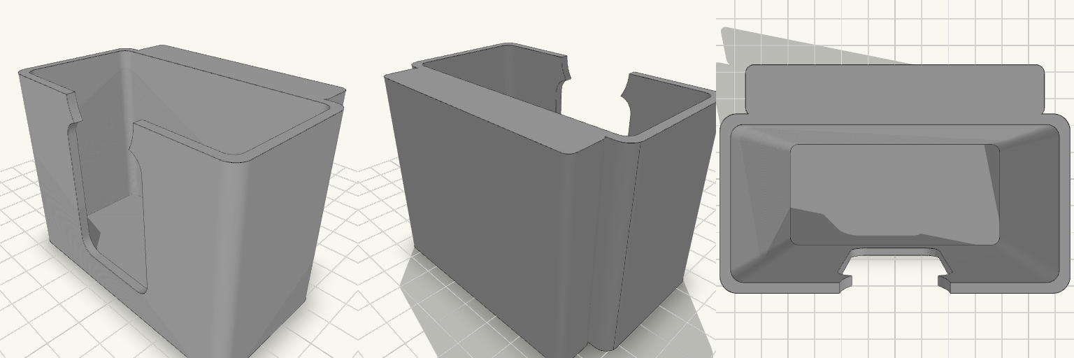
A belt-worn holster cup for a 5 m tape measure, sized for a body of about 75 × 75 × 35 mm with 2 mm of total clearance. A vertical window in the front lets you read the size label without pulling the tape out, and a round thumb scoop at the top edge makes it easier to grip and lift. A loop on the back takes a belt. The cup is open at the top and covers the lower 80% of the tape (60 mm). Outer size is 82 × 42 mm, with 2.5 mm walls and a 2.5 mm floor. Remix hooks Tape size: the tape width, height and thickness (75 / 75 / 35 mm) and the 2 mm clearance are the main numbers. Change them and the cup, loop and window all follow. Other tape brands or 3 m / 8 m sizes are a quick swap. Cup height: set at 80% of tape height (60 mm). Lower it for easier draw, raise it for a more secure hold. Label window: 30 mm wide, with rounded ends, centred on the front. Widen it for a bigger label, or move it to the side for a tape with an offset label. Thumb scoop: 26 mm diameter cut at the top front. Shrink it for a snugger hold. Belt loop: the slot is about 5 mm deep and the loop spans the back at 70 mm wide. Thicker or wider belts need a deeper slot, which is the first thing worth testing against your own belt. Wall thickness: 2.5 mm. Go thicker for rigidity, or thinner to save material. Pairs well with A flexible filament such as TPU for a grippier cup, or PETG for a stiffer loop. A second window on the back or side if you want to read the metric scale as well. A small retention tab or friction bump inside the cup rim if the tape needs a firmer hold.
Small Block 15x4x4 mm
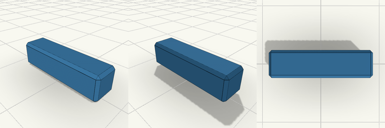
What it's for A small solid block for use as a spacer, shim, test piece or placeholder. Dimensions Length: 15 mm (X) Width: 4 mm (Y) Height: 4 mm (Z) Edges chamfered 0.4 mm Remix ideas Add a through hole for a screw or string. Increase the chamfer for a softer look. Engrave a label on the front face.
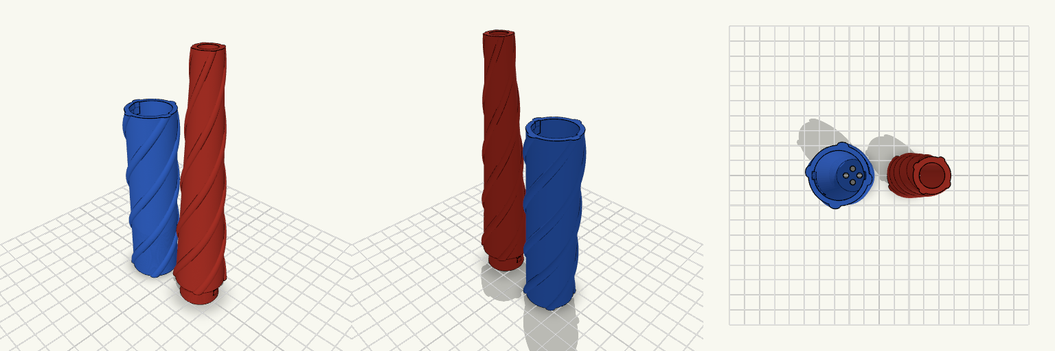
Zauberstab final
What it's for Zweiteiliger Zauberstab aus Griff und Spitze, gebaut für eine UV-Taschenlampe im Griff. Der Griff bietet 97 mm Innenhöhe, sodass die Lampe vollständig unterhalb des Bajonettverschlusses sitzt; die hohle Spitze lässt das UV-Licht oben austreten. Außen liegt ein glatter Kern mit vier runden, spiralförmig aufgelegten Teigsträngen, die wie um den Stab gelegte Teigbahnen wirken. Ein innenliegendes Bajonett mit Rastnocke hält die Teile bündig zusammen und sichert gegen unbeabsichtigtes Aufdrehen. Vier Bodenlöcher im Griff erlauben den Zugang zum Druckknopf der Lampe. Dimensions Griff: 99 mm hoch, 97 mm Innenhöhe, Innen-Ø 21,8 mm; Lampe sitzt unterhalb der Bajonettnut. Spitze: 135 mm inkl. Zapfen; Lichtkanal von 18 mm unten auf 9 mm oben; Wand im Bajonettbereich mindestens 1,5 mm. Außen: glatter Kern Ø 26,4 mm; vier Stränge unten ca. 5 mm breit und 1,4 mm hoch, nach oben ca. 2,5 mm breit und 0,7 mm hoch; größtes Außenmaß ca. Ø 29,2 mm. Bajonett: innenliegende Nut im Griff, Nasen an der Spitze, Rastnocke; Einführschlitz bis zur Oberkante; Muster auf die 45°-Endstellung abgestimmt. Boden: vier Löcher Ø 3,75 mm, enger zur Mitte gesetzt. Print notes Griff und Spitze werden getrennt gedruckt und über den Bajonettverschluss verbunden. Die Außenkontur ist glatt ausgelegt; das Relief der Teigstränge liegt als aufgesetzte Struktur darüber. Für eine saubere runde Außenwand ist eine feine Auflösung sinnvoll. Die Rastnocke ist als spürbarer Widerstand ausgelegt; je nach Drucker und Material kann der Eingriff straffer oder weicher ausfallen. Remix ideas Anzahl der Stränge oder Windungszahl über die Höhe ändern. Strangquerschnitt dicker für kräftigeres Relief oder dünner für eine glattere Oberfläche. Griffhöhe und Lichtkanal an eine andere Taschenlampe anpassen. Rastnocke stärker oder schwächer auslegen.
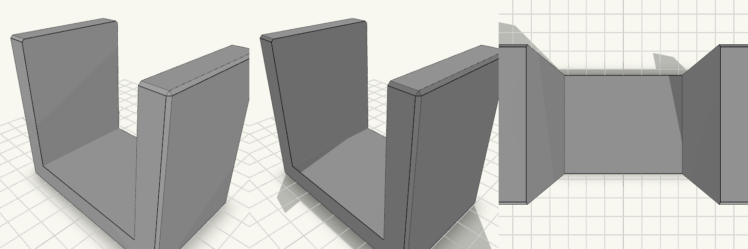
U profilis, 60 mm tarpas, aukštos sienelės
U formos laikiklis, kuriame detalė neslysta į šonus: 60 mm tarpas tarp sienelių, 10 mm sienelės ir dugnas, 50 mm pagrindo plotis. Matmenys Vidinis tarpas: 60 mm Sienelių ir dugno storis: 10 mm Sienelės virš dugno: 60 mm (pailgintos 50 mm) Bendras dydis: 80 × 50 × 70 mm Spausdinimas: dugnu ant stalo, atramų nereikia
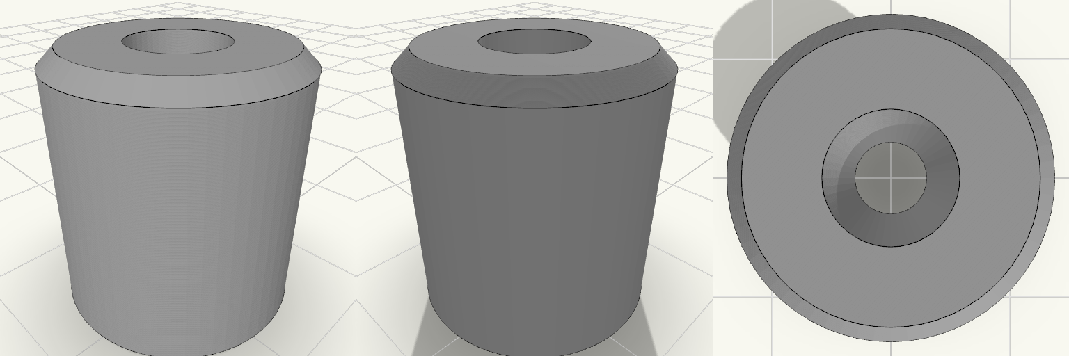
Kleiner Puck: Zylinder-Distanzstück mit 6-mm-Bohrung
Ein kleiner Puck aus der Maschine: 15 mm im Durchmesser, 15 mm hoch, mit einem sauberen 6-mm-Loch, das einmal komplett durchgeht. Die beiden Stirnflächen laufen nicht scharf aus, sondern sind mit einer 1-mm-Fase im 45°-Winkel gebrochen — das gibt dem Teil seine leicht abgerundete Silhouette und lässt es sauber aufliegen, statt mit einer Kante zu kippen. Genau die Art von Kleinteil, das in der Werkstattkiste fehlt, wenn irgendwo Abstand gehalten werden muss — als Distanzstück, Buchse oder Hülse zwischen zwei Flächen, durch die eine Schraube, eine Achse oder eine Gewindestange läuft. Auf einen Blick Durchmesser: 15 mm Höhe: 17 mm durchgehende Bohrung: 6 mm Wandstärke rundum: 4,5 mm Fase außen oben und unten: 1 mm × 45° steht auf dem Druckbett ohne Stützen und ohne Brim Die Wandstärke von 4,5 mm macht den kleinen Körper stabil genug für Schraubverbindungen und Abstandshalter, ohne dass er zum Klotz wird. Das 6-mm-Loch nimmt M6-Schrauben, Gewindestangen und Achsen auf; die Höhe von 17 mm lässt sich bei Bedarf leicht skalieren, wenn mehr Abstand gebraucht wird. Die Fase sitzt nur außen — die Bohrung bleibt über ihre ganze Länge zylindrisch und führt Schraube oder Achse gerade durch. Ein stilles, universelles Teil — eines, das man in mehreren Größen druckt und dann in der Schublade hat, wenn es darauf ankommt.
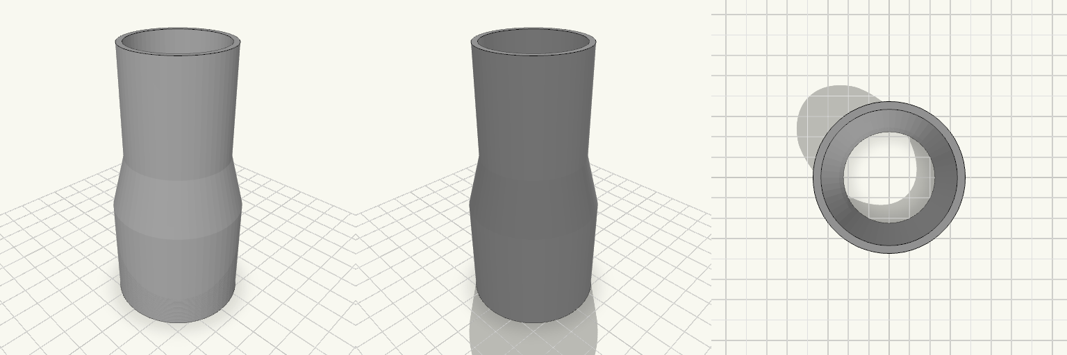
Makita Dust Suction Adapter Tube V2
This single-piece tube adapts a Makita dust port or hose to a smaller connection. It runs 100 mm overall: a 40 mm straight section at 49 mm outer diameter, a 20 mm conical transition, and a 40 mm straight section ending in a 35 mm bore. The wall is 2 mm, so the 49 mm end has a 45 mm bore that narrows to 35 mm at the small end, which measures 39 mm across the outside. Because the fit is defined by those two ends, they are the first thing to check against the real hose and tool port — printed tubes commonly come out slightly off. Remix hooks End sizes: The 49 mm outer diameter and the 35 mm bore are the dimensions to tune. Shifting either by a few tenths of a millimetre is the normal way to account for printer variation and the actual fitting. Wall thickness: The 2 mm wall is a starting value. A thicker wall stiffens the tube and shrinks the bore; a thinner one gives more internal clearance at the same outside size. Bore profile: Here the 49 mm end starts at a 45 mm bore and steps down to 35 mm. Running the 35 mm bore through the whole length is the obvious variant if you want a straight-through passage. Transition: The 20 mm cone can be shortened for a more abrupt step or lengthened for a gentler taper. Ends: Add a lip, retaining ring, or chamfer at either end if the hose or tool port needs a positive stop. Length: The 100 mm overall length is a choice, not a constraint. Shorten it to reach into tight spots or extend it to clear an obstruction. Pairs with: A Makita hose on one side and a smaller vacuum or tool port on the other, with the end sizes adjusted to match whatever you actually have.
Need a part that doesn't exist yet?
Start building →