3D-printable home fixtures & hardware
Brackets, cabinet pulls, knobs, doorstops, racks and mounts built to real measurements. Browse what makers built, or describe the exact fixture you need and Printy makes it.
Need one that fits your exact measurements? Start building →
Newest
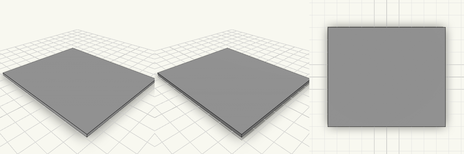
plaque support avant araignee
Une plaque plane de 93 × 79 mm sur 2 mm d'épaisseur : le morceau de base qui remplace la découpe qui n'existe pas dans le bon format. Elle s'imprime à plat, sans support, et sort avec des arêtes vives — à chanfreiner ou percer plus tard si besoin. Ce qui décide de l'usage Dimensions au sol : 93 × 79 mm Épaisseur : 2 mm — assez rigide pour ne pas gondoler, assez fine pour se glisser sous un élément Contour : arêtes vives, aucun chanfrein, aucun trou de fixation Orientation : posée à plat sur le plateau, aucun surplomb Impression Sans supports, face plane sur le plateau 2 mm se remplissent bien en 4 à 5 périmètres ; une dizaine de couches suffit PETG ou PLA selon la rigidité voulue ; le PETG encaisse mieux la flexion
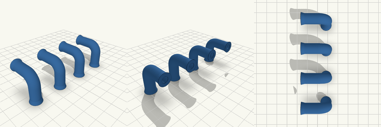
90 Degree Water Elbow, 5 mm Bore
A set of four identical 90 degree elbow fittings for water lines, each with a 5 mm inside diameter and a 2 mm wall. Each elbow has a smooth curved bend and two straight 14 mm legs. A small ridge at each leg end helps hold a tube in place. Inside diameter: 5 mm Outside diameter: 9 mm (2 mm wall) Leg length: 14 mm each Bend radius: 8 mm at the centreline Quantity: 4 identical elbows, spaced 25 mm apart
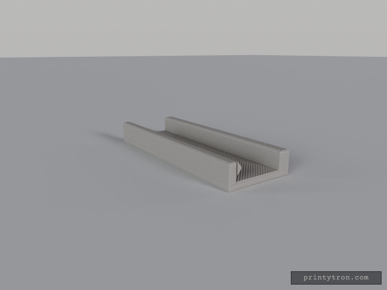
Fly Screen Frame Snap Lock for Wall Gap
A fly-screen frame that keeps popping out of the gap between it and the wall is the annoyance; this clip holds it in line without screws. The frame slides in along the channel from either end, past ramps on a thin flexible arm — it gives way to a deliberate pull but stays put in a gust — and the back carries a glue strip so the clip sits flat against the wall. Fit and hold Channel: 10.2 mm wide for a 1 cm frame, 0.2 mm clearance. Entry: open at both ends, so the frame slides in along the 40 mm length; the arm's lip is ramped down at both ends to start it easily. Front arm: 1.6 mm thick and flexible, fixed only along its base, so the frame opens up easily and still holds in wind. Back wall: rigid, no lip — it stays clear of the sliding frame and only the arm does the holding. Glue recess: 0.8 mm deep and 30 mm long on the back, so the glue strip sits flush and the clip lies flat. Size: 40 × 14.3 × 5 mm, matching the 0.5 cm gap between wall and frame. Use PETG for the flexing front arm — it takes the repeated opening and closing better than a brittle filament, and the stiffness of the arm is what decides whether the frame holds or rattles loose.
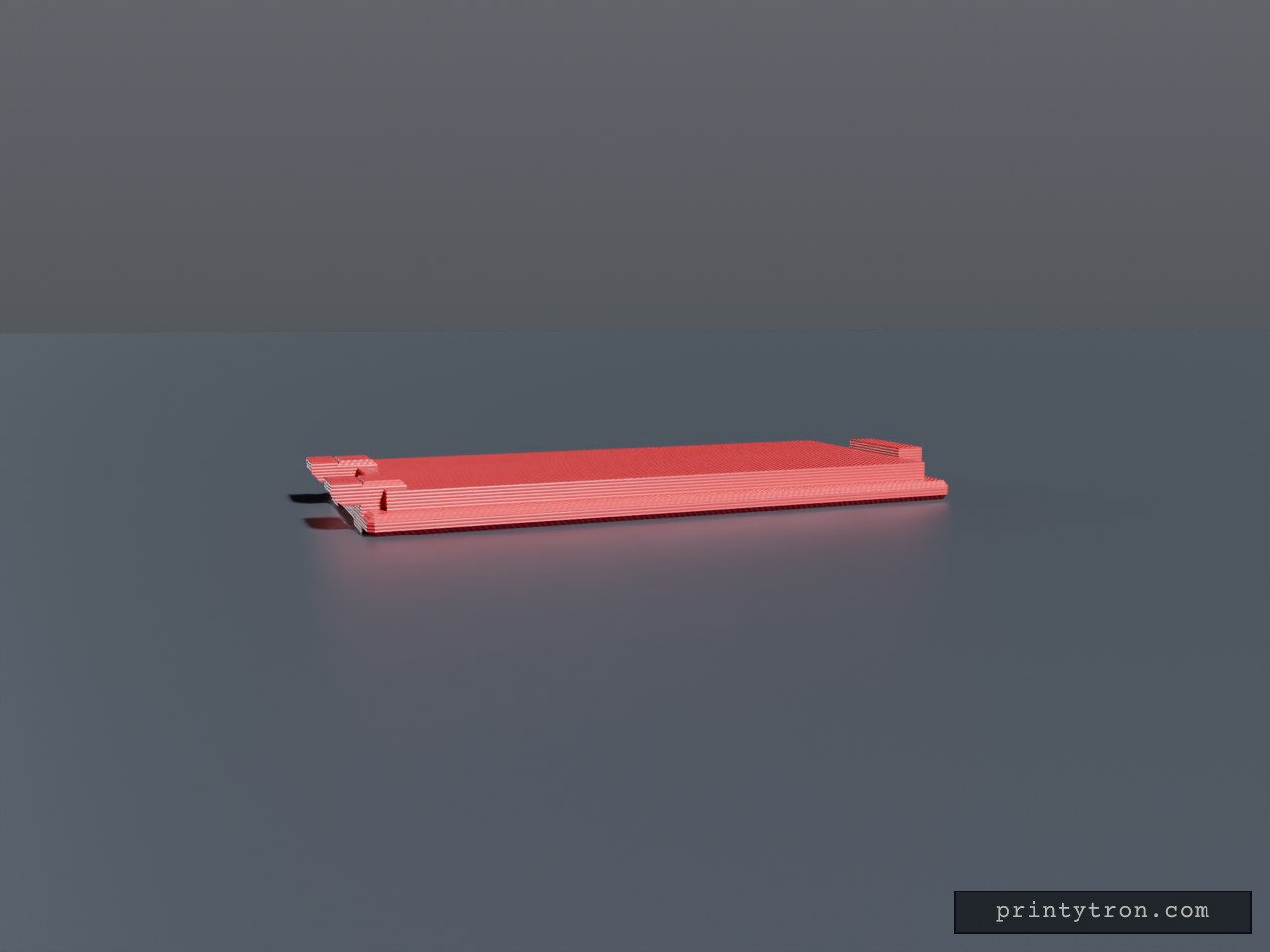
Bug Zapper Battery Cover 27.65 x 60 mm
Sliding battery compartment cover plate for a bug zapper, 27.65 x 60 mm. A locating lip sits in the compartment opening, a latch tab sits at one end, and two low retention tabs at the opposite end keep the cover from falling out. Plate: 27.65 x 60 x 2 mm, chamfered edges Lip: 23.65 x 56 mm, 3.8 mm total height Retention tabs: two, 5 mm wide, flush with lip height, at X = ±8 mm Latch tab: 10 mm wide at the +Y end Grip grooves on the outer face Dimensions are estimates; verify against the original opening
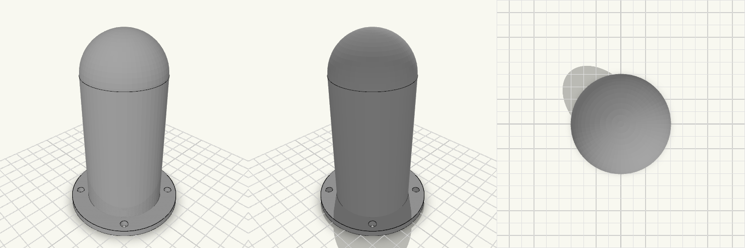
Antenna Cover With Mounting Flange
An antenna protective cover that keeps weather and knocks off the antenna: a hollow cylinder with a domed top, open at the bottom, on a flat bolt-down flange. Total height: 115 mm including the 4 mm flange Body: 50 mm outer, 46 mm inner diameter (2 mm wall), dome radius 25 mm blending tangentially into the cylinder Flange: 72 mm diameter, 4 mm thick Holes: four 5 mm through-holes in a square, 43.1 mm between adjacent centres Print: open end down on the flange, no supports needed, 3+ perimeters recommended
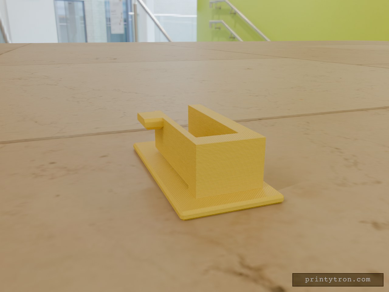
Glue-On Snap Latch for Fly Screen Frames
A fly screen frame that lifts out of its catch every time the door moves needs a latch that holds it and lets go on demand. This one glues to the wall, the frame presses into the slot and snaps past the hook, and a thumb tab on the outside of the arm pulls the hook clear. One hand does both jobs — no second hand holding the frame, no screwdriver. Fit Slot: 10.4 mm wide, sized for a 10 mm frame with 0.4 mm clearance. Base plate: 50 × 24 mm, 2 mm thick, with two shallow relief pockets underneath to hold the glue. Snap arm: 30 mm long, 1.8 mm thick. Printing One piece. No screws, no loose parts, nothing to assemble. Print standing as modelled, so the layers run across the arm's bend rather than along it. PETG suits the flex the snap arm needs. Measure the standoff between wall and frame before gluing: the base plate is 2 mm thick, so it sits in the gap rather than spanning it. Snap strength and tab size are the two things to adjust if the catch is too stiff or too easy for the frame you have.
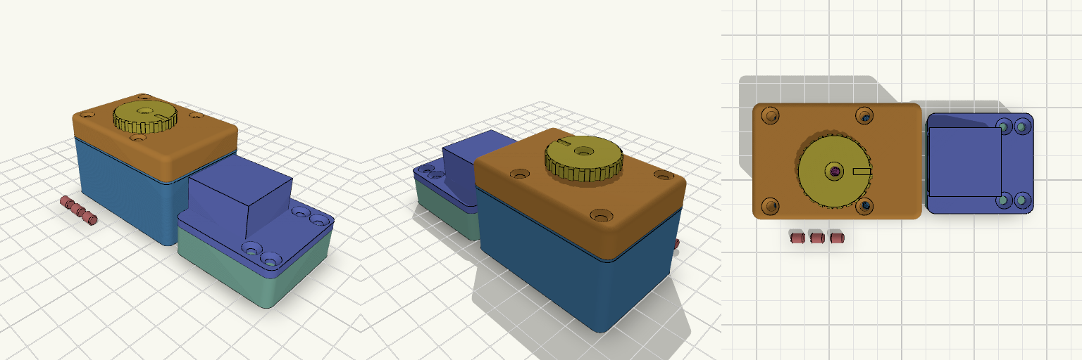
Tranca Industrial de Sobrepor com Ferrolho
Tranca de sobrepor no estilo cofre de bancada: ferrolho deslizante, manípulo de meia-volta e receptor com bolso de entrada chanfrado. Todas as peças são impressas separadas e se encaixam na montagem, com folgas já embutidas para FDM. Base, tampa, ferrolho, eixo com braço, disco do manípulo, receptor e calço. Pino do braço Ø4 × 5 em PETG, com 3 sobressalentes deitados. Furo do pino no braço Ø4.0, para encaixe com uma gota de cola. Altura total: 36.0 na tampa e 40.4 no topo do disco.
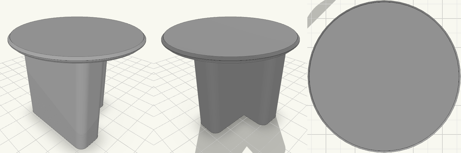
T-Post Cap With 2.5-Inch Round Platform
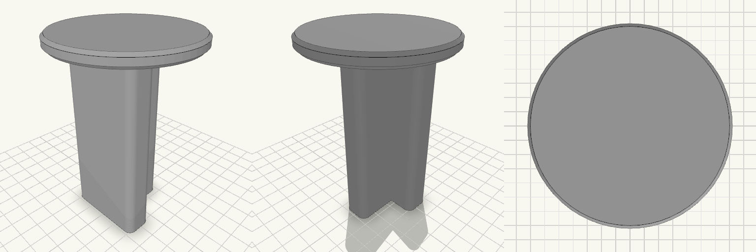
A slip-on cap for a steel T-post: 4 in tall, with a T-shaped socket that drops over the post and a 3 in round platform, 1/4 in thick, on top. Fits Steel T-posts, matched to the T-socket below. The socket is a T: a 36 mm crossbar, 7 mm wide at the stem entry, with a 7 × 30 mm stem running down, and a 4 mm wall following that T all the way around. Takes the place of a plain post cap and adds a flat, 3 in round surface on top of the post. Check before printing The socket is the whole fit, and its numbers are a starting size, not a standard — T-posts differ in flange width and web thickness between manufacturers and post weights. Measure the post you intend to use across the crossbar, across the stem, and across the full depth, then set the socket to those sizes plus a little clearance for paint and burrs before you commit filament. Nothing else on the part affects fitment. Does not fit Round posts, wooden 4x4 posts, or any post without a T cross-section. T-posts whose crossbar or stem is wider than the socket above — T-post profiles are not interchangeable, so do not assume a fit from the post name or the post weight alone. The cap prints as a single piece, 76 × 76 × 102 mm overall.
T-Post Cap With 3-Inch Round Platform
A slip-on cap for a steel T-post: 4 in tall, with a T-shaped socket that drops over the post and a 3 in round platform, 1/4 in thick, on top. Fits Steel T-posts, matched to the T-socket below. The socket is a T: a 36 mm crossbar, 7 mm wide at the stem entry, with a 7 × 30 mm stem running down, and a 4 mm wall following that T all the way around. Takes the place of a plain post cap and adds a flat, 3 in round surface on top of the post. Check before printing The socket is the whole fit, and its numbers are a starting size, not a standard — T-posts differ in flange width and web thickness between manufacturers and post weights. Measure the post you intend to use across the crossbar, across the stem, and across the full depth, then set the socket to those sizes plus a little clearance for paint and burrs before you commit filament. Nothing else on the part affects fitment. Does not fit Round posts, wooden 4x4 posts, or any post without a T cross-section. T-posts whose crossbar or stem is wider than the socket above — T-post profiles are not interchangeable, so do not assume a fit from the post name or the post weight alone. The cap prints as a single piece, 76 × 76 × 102 mm overall.
Garden-Plumbing Workhorse: BSP to 3/4 Hose Barb
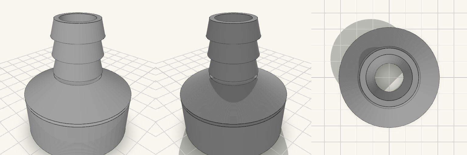
A straight-line adapter that bridges a 1-1/4" BSP female threaded socket to a 3/4" hose barb, with a tapered shoulder carrying the eye from the wide threaded end down to the narrow ridged nozzle. It reads like a piece of honest utility hardware: a ring of 11 TPI thread at one end, three crisp ridges at the other, and a 15 mm bore running clean through a compact 55 mm body — short enough to tuck into tight pump and tap arrangements without a loop of hose fighting for room. The barb's ridges ramp up gently from the tip and widen toward the body, then drop off in a sharp step — the hose slides on without a fight, and the step keeps it from backing off again. Design notes: 1-1/4" BSP female socket, 11 TPI, 41.91 mm major diameter, 18 mm deep Tapered transition from the socket down to the barb 19 mm barb with three retention ridges, 7 mm tall and spaced 8 mm apart, narrow at the tip and widening to a step at the body side, for 3/4" hose 15 mm bore through the full length; 55 mm overall Prints as a single piece, sitting upright at roughly 50 × 50 mm on the plate Fit and sealing: The thread is modelled at nominal size with no added clearance, so a first test fit against the male fitting is worth doing — if it binds, opening it out by 0.2–0.4 mm is the easy fix. For a watertight joint, wrap the thread with PTFE tape or seat a flat washer against the socket floor. The shortened barb leaves less hose length to grip; a hose clip just behind the final ridge makes up for it. Pairs naturally with garden hose, pump outlets and tank fittings.
Tranca de Sobrepor com Tampa Removível
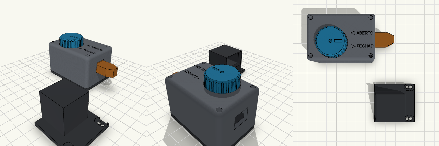
Tranca de sobrepor compacta (56,5 × 39 × 35,6 mm) em que toda a parte superior do corpo é uma tampa única. Ao retirar os 4 parafusos M3, a tampa sai inteira e deixa o interior à mostra. O conjunto inclui base com piso de 3 mm, ferrolho, manípulo elevado com serrilha, pino de aço Ø4 mm e receptor separado. Ideias para remix Altura da divisão: a tampa começa no piso (3 mm). Subir esse corte deixa paredes na base e uma tampa mais rasa. Manípulo: disco Ø24 mm com 8 mm acima da tampa. Uma alavanca alongada dá mais braço. Fixação: 4 furos Ø3,4 mm (34 × 29 mm) com rebaixo, para parafusos 3,5 × 25 mm. Combina com: receptor de 40 × 38 mm, que pode ser aparafusado na porta ou no batente.
253 x 126 x 150 mm Rectangular Trash Bin
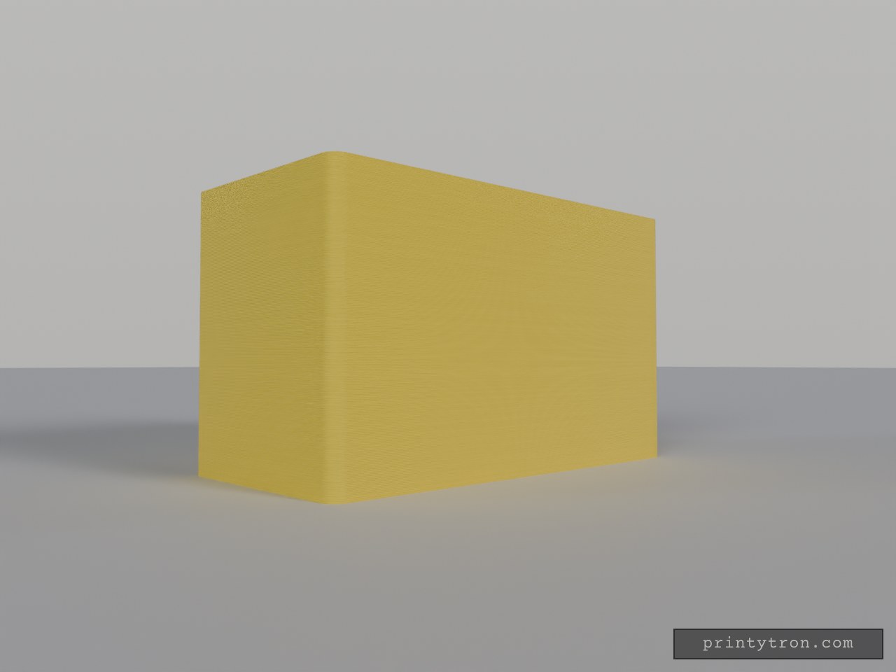
Open-top rectangular trash bin with 4 mm walls and a 3 mm floor, sized 253 mm long, 126 mm wide and 150 mm tall (outside dimensions), with rounded vertical corners. Fitment notes Measure first: the 253 mm length exceeds a 220 mm print bed. Check your bed's usable X/Y before printing. Fits: any liner or bag that suits a 245 x 118 mm inside opening. Does not include: a lid, handle or drainage holes. Inside size: 245 x 118 mm, 147 mm deep.
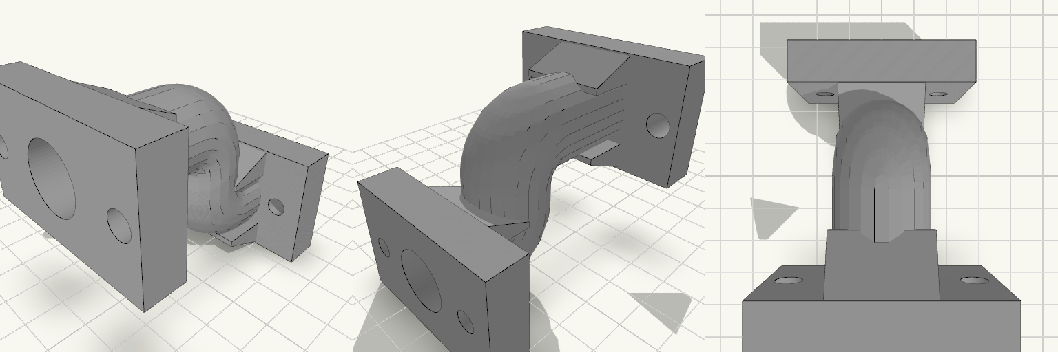
Ansaugstutzen Hercules
Rohrverbindungen, die aus einer Platte austreten, knicken an der Kante gern weg — dieser Rohrwinkel verstärkt genau dort mit Keilen über und unter dem Rohr. Er verbindet eine 45 × 30 mm große Platte mit einer 50 × 30 mm großen Platte, weitet den Innendurchmesser von 15 auf 16 mm und lässt die seitlichen Schraublöcher frei. Das Rohr ist an beiden Enden durchgehend offen: Die Bohrung läuft von der 15-mm-Seite bis zur 16-mm-Seite komplett durch Platte und Rohr. Platte 1: 45 × 30 × 10 mm; Mittelloch 15 mm; zwei 5-mm-Löcher bei ±15,5 mm vom Mittelpunkt. Platte 2: 50 × 30 × 10 mm; Mittelloch 16 mm; zwei 6-mm-Löcher bei ±20 mm. Rohr: 15 mm innen, 3 mm Wandstärke (21 mm außen), 25 mm nach oben und 20 mm nach vorn, zwei 90°-Biegungen; auf den letzten 20 mm weitet sich der Innendurchmesser auf 16 mm. Offene Enden: Bohrung an Platte 1 mit 15 mm und an Platte 2 mit 16 mm, jeweils komplett durch Platte und Rohr. Verstärkung: An beiden Platten sitzt je ein Keil über und unter dem Rohr, nur so breit wie das Rohr; seitlich bleibt Platz für die Löcher. Gesamtgröße: 50 × 65 × 55 mm auf dem Druckbett.
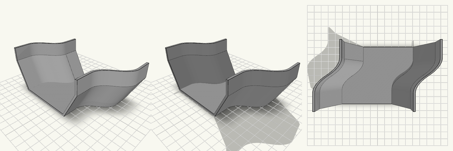
114mm Square Gutter S-Bend Section
A square-profile gutter offcut with an S-bend that pulls the run 30 mm closer to the wall, replacing a straight section that sits too far out from the fascia. Overall width 114 mm, depth 57 mm, wall 2.4 mm Base flat 73 mm wide, vertical sides 18 mm tall, angled sections between Length 80 mm: 20 mm straight at each end, 40 mm S-bend between Offset 30 mm toward +X (wall side) Open-top hollow channel, end to end; print upright on the base, supports not needed
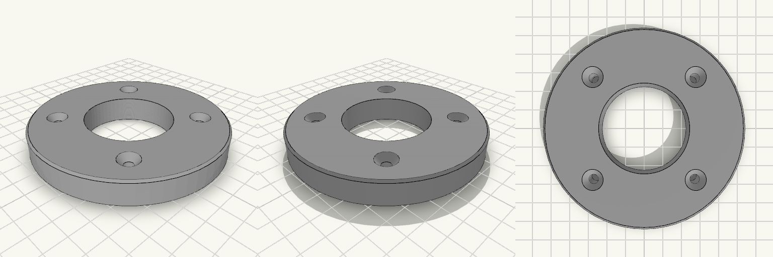
100 mm OD Flange, 45 mm Bore
A flat round flange, 100 mm outside diameter and 13 mm thick, with a 45 mm bore straight through the middle. Four 5 mm holes sit on a 72 mm bolt circle at 45°, 135°, 225° and 315°, countersunk from the top face and 10.5 mm across at the rim. The outer edges carry a 1 mm chamfer, so there is no sharp rim to catch on. What it fits Bore: 45 mm nominal — measure the shaft, tube or spigot it goes over with calipers first. A printed 45 mm bore comes out undersized on most machines, so plan on reaming or drilling to size. Bolt pattern: four holes on a 72 mm bolt circle, at the diagonal positions rather than at 12/3/6/9 o'clock. Confirm the orientation of the mating part before drilling anything. Fasteners: 5 mm clearance with a countersink 10.5 mm across, sized around M5 flat-head screws so the heads sit at or just below the top face. Longer screws will not sit flush, and the 13 mm body sets how much thread you have to play with. Face: the 100 mm diameter leaves roughly 27.5 mm of material between the bore edge and the outer edge. What it does not have No hub and no raised face — it is a plain flat disc, so it will not self-centre on a register. No thread, no taper and no keyway in the bore. No O-ring groove or gasket recess; sealing has to come from the mating faces or a separate gasket. No second bolt pattern — if the part you are mating to has six or eight holes, or a circle other than 72 mm, this will not bolt on. Before you print Measure the bolt circle and the hole positions on the part you are mating to, centre-to-centre, and check that the four-hole diagonal layout matches. Also check that 13 mm of thickness clears whatever sits behind the flange, since the countersinks eat into the top face and leave less material under the heads than a plain 13 mm plate would suggest. Prints flat on the bottom face with no supports; the chamfer and the bore both come out clean laid down that way, and the countersinks form on the top surface without bridging.
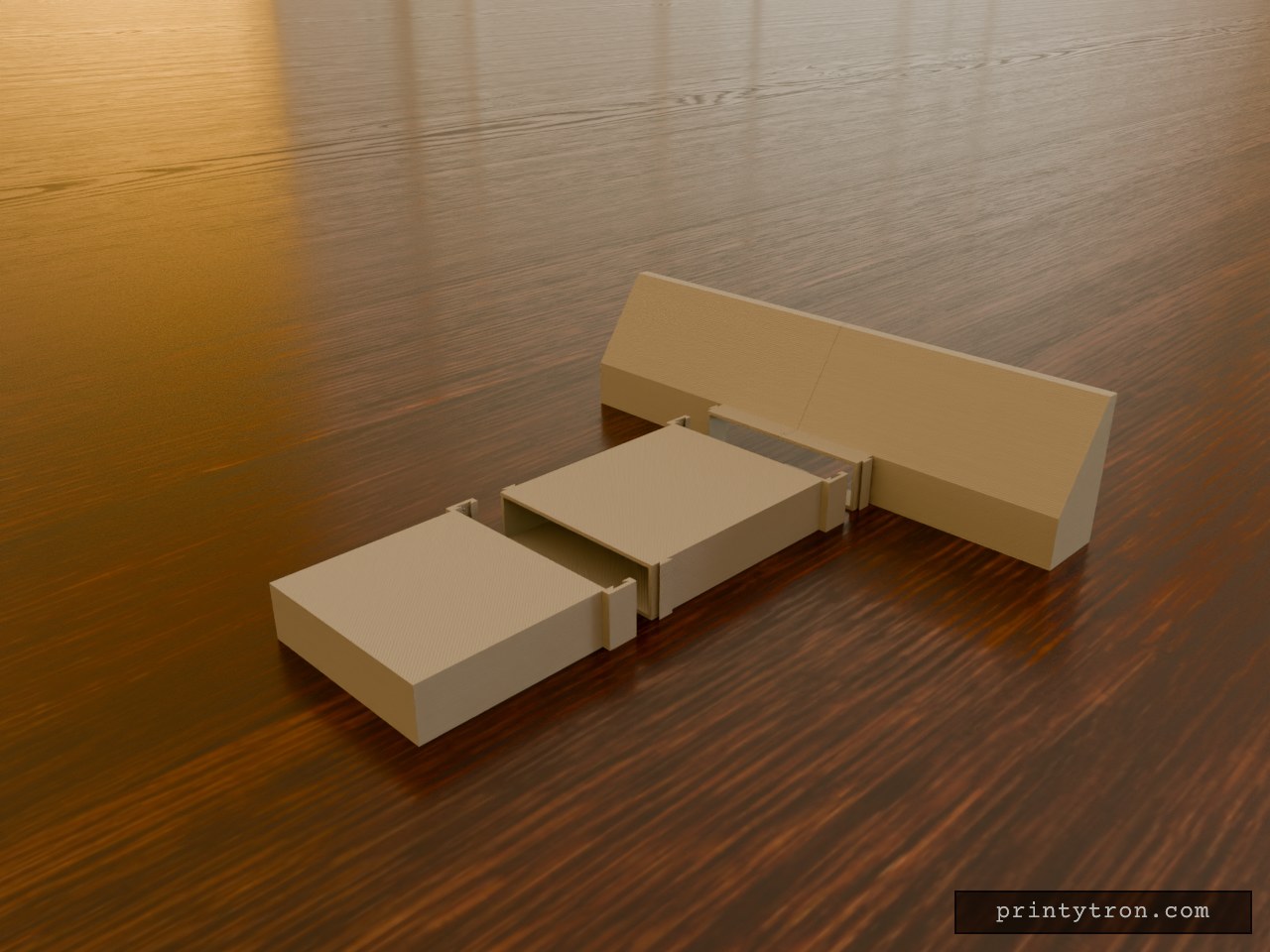
Four-Piece Baseboard Register Hood and Duct Kit
This is a four-part replacement hood and duct kit for a baseboard HVAC register: two hood halves, a straight extension tunnel, and a 90-degree side-turn end cap. When the hood halves are joined, the hood measures 450 mm wide along the wall, 80 mm deep, and 115 mm tall. The rear and bottom are open to take air from the baseboard void; the sloped front funnels that air into a centered horizontal nozzle at the lower front edge. The nozzle is 150 mm wide, 40 mm tall, and projects 20 mm forward. All four parts print separately and slide together with dovetail joints. The extension and cap sit on the plate beside the hood halves, not pre-assembled. The sliding joints use 0.3 mm clearance per side, and the chunk and cap sockets have small friction bumps. For an air-tight run, add foam gasket tape or silicone along the socket edges; test-print one joint before reducing clearance below 0.3 mm. Hood Specifications Printed hood halves: HoodLeft and HoodRight, joined by a central vertical sliding dovetail with 0.3 mm clearance. They slide together vertically along the seam. Shell: nominal 3 mm walls, with a 24 mm wide band across the center of the sloped roof and front wall thickened to 8 mm so the dovetail cuts through solid material. Joined hood footprint: 450 × 80 × 115 mm. Rear wall side and bottom floor are open. Outlet nozzle: 150 × 40 mm, projecting 20 mm forward. Nozzle side tracks: male dovetail on each outer side, 6 mm wide at the root and 12 mm at the tip, 3 mm deep, with 45° flanks. The wider printed hood half measures about 228 mm across, so check print-bed width. Extension Chunk Extension_Chunk is a straight hollow tunnel, 150 × 40 mm outside and 200 mm long, with 3 mm walls. Inlet socket: the first 20 mm has no top or bottom plate so it drops down over the nozzle; its side walls carry dovetail slots held 0.3 mm off the nozzle tracks. Small friction bumps sit at the top and bottom, two per side, to resist lifting off; they add friction rather than a positive click or seal. Outlet tracks: the same male dovetail as the hood nozzle, set 10 mm back from the end so the next chunk's socket fits over them. The socket end measures about 162.6 mm outside to house those slots. The tunnel has a bottom floor; it keeps the channel stiff and the sliding joints aligned over uneven flooring. Thinning that floor to 2 mm saves plastic; removing it will leak along the bottom. Chain as many chunks as the run needs; each one slides on vertically and can be swapped or added without tools. The chunk prints as a separate part alongside the hood halves, not pre-assembled. Side Turn Cap SideTurnCap is a 90-degree flat elbow end cap, nominal 150 mm wide, 40 mm tall, and 160 mm long, with 3 mm walls. Inlet: the same 20 mm dovetail socket as the chunk, open top and bottom, sliding vertically onto the chunk's outlet tracks with 0.3 mm clearance. Small friction bumps sit at the top and bottom, two per side, to resist lifting off; they add friction rather than a positive click or seal. Front end: closed off completely. Vent: one entire side wall is open as the exhaust; the top and bottom plates stay intact. Vanes: three internal quarter-circle turning vanes, 2 mm thick, with radii of 36, 72, and 108 mm, running the full interior height to turn airflow 90° out the side opening. The inlet gaps are an even 36 mm, including the gap to the far wall. Flip: the top and bottom are identical and symmetrical, so turning the cap upside down directs air out the other side. The socket end measures about 162.6 mm across; the cap prints as a separate part beyond the chunk on the plate.
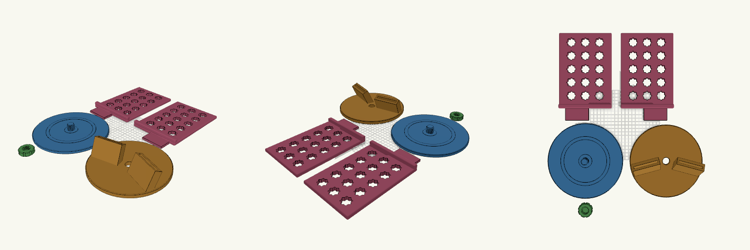
Swivel Quran Stand
A rehal-style book stand with a turntable base and two backward-leaning panels, pierced with eight-pointed khatam stars. The stars cut filament use while leaving a solid perimeter frame. A narrow gap between the panels takes the book's spine, and a rounded lip along the bottom edge holds the pages. Base: 214 mm disc with a coarse threaded pivot post and low bearing rings. Swivel carriage: spins 360° on the post. Two angled slot blocks are printed into it, with no supports needed. Retaining cap: screws onto the post to lock the carriage on, no metal or glue. Panels: two mirrored panels, 150 × 215 mm, with a flat tongue that slides into each carriage slot. Designed around a 170 × 240 mm book of about 1.5 kg, on a 220 mm bed with a 0.4 mm nozzle. Panels print flat on their backs. Flip the cap so its top is on the bed.
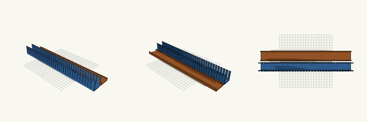
Finger Trunking with Snap-On Lid
Finger trunking that blocks access to your mounting holes is a problem. This one has floor slots cut where the screws and the access hole need to be, plus a snap-on lid. The walls are free-standing fingers with barbs at the tips. The lid's inward lip clips under the barbs. Size: 340 × 30 × 35 mm, with 2 mm walls and a 2 mm floor. Fingers: 4 mm gaps on a 10 mm pitch. M3 slots: Four slots, 3.4 mm wide and 5.4 mm long. They sit at 10, 100.75, 191.5 and 282.25 mm from the left end, 90.75 mm apart. Access hole: 7 mm diameter, 201.5 mm from the left end. Slot line: All slots sit 10.786 mm toward +Y from the centreline. Printing: The trunking is longer than most print beds. Print it diagonally or split it. The lid lip is a small overhang when printed flat.
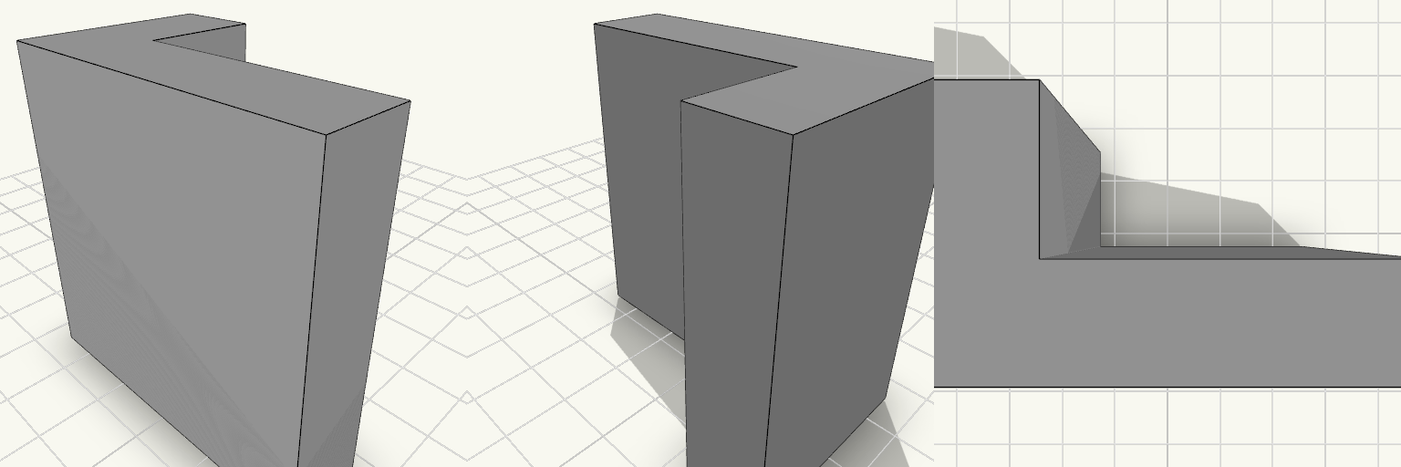
Anglewright — 90° L Profile
Anglewright is a clean 90° L profile with unequal legs: 2 in along one axis and 1.2 in along the other, standing 2 in tall. Both legs are 0.5 in thick, giving a simple right-angle section for corner bracing, spacing, or building up a frame. The form is a single continuous L, so the shape itself carries the function. Dimensions Overall height: 2 in (50.8 mm) Leg lengths: 2 in × 1.2 in (50.8 mm × 30.5 mm) Leg thickness: 0.5 in Corner angle: 90° Print notes At 2 in tall the profile sits comfortably within a typical print bed, so it can be printed standing up on its end with no special base. Lying on its side also works and keeps the flat L section stable on the plate. No supports are needed either way; the 0.5 in legs give plenty of contact area. Features Single-piece right-angle profile with no assembly Unequal legs for mixing offsets in two directions Small enough to print several at once for a set of matched braces
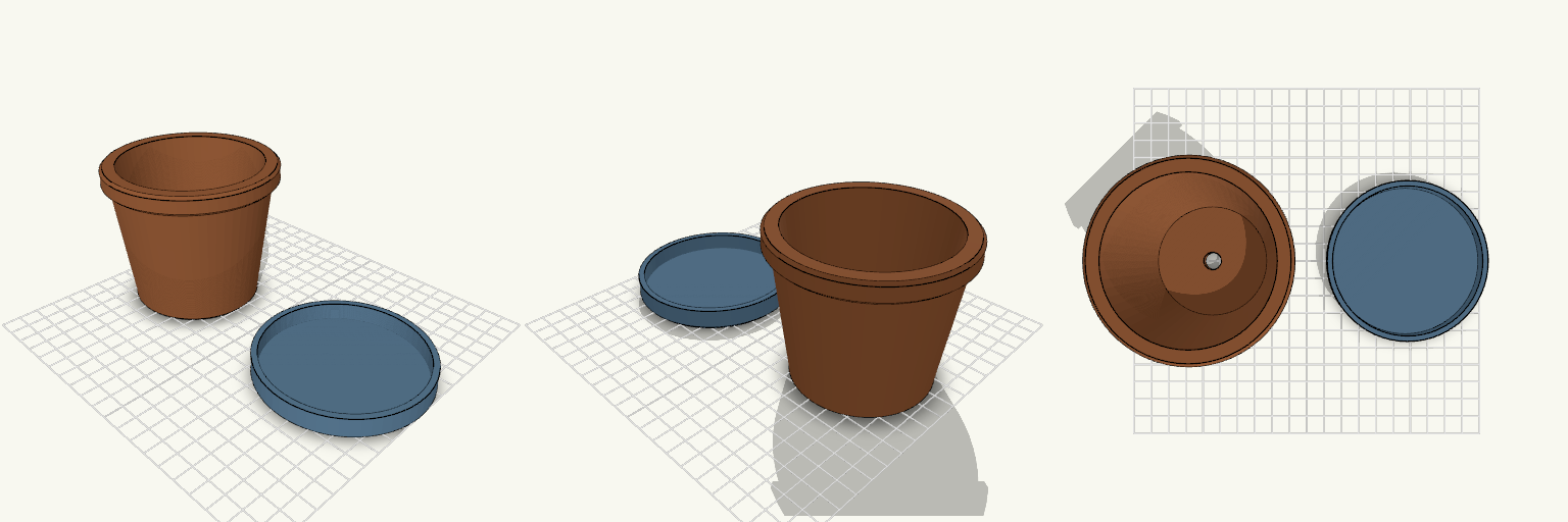
Cactus Pot With Drainage Hole
A cactus pot with a drainage hole, so water leaves the soil instead of rotting the roots. A separate saucer catches the runoff so it doesn't end up on the windowsill. Key numbers Pot: 70 mm base, 90 mm opening, 75 mm tall, 96 mm rim lip Drainage hole: 10 mm diameter, centred in the 6 mm floor Saucer: 90 mm diameter, 12 mm tall, 2.5 mm floor. The pot's 70 mm base sits inside it. Print: no supports needed, both pieces print upright. 0.2 mm layers, PETG or PLA.
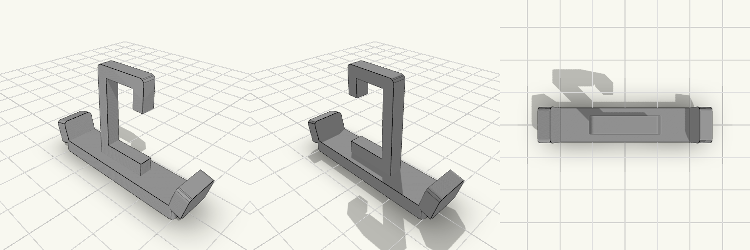
Kampas — Mini pakaba su pakeltais galais
Kompaktiška vaikiškos suknelės pakaba su stačiakampe kilpa ir stipriai pakeltais galiukais, kad petnešėlės nenuslystų. Savybės Plotis 10 mm Galiukai pakelti 45° kampu Stačiakampė atvira kilpa Plokščia apatinė dalis pailginta 0,8 mm
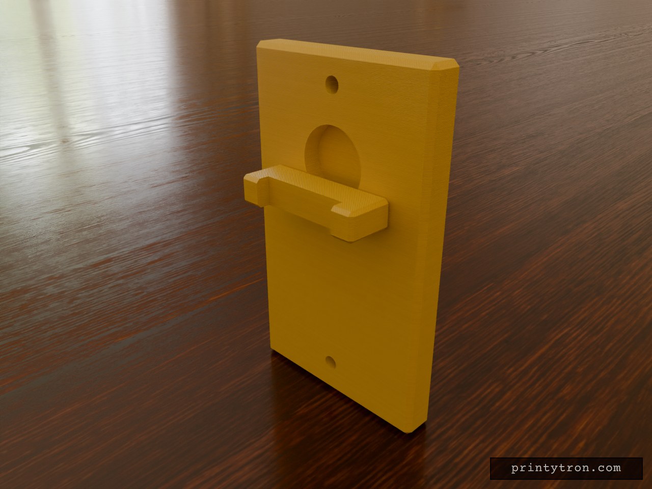
Capstop — Magnetic Wall Bottle Opener
Capstop is a wall-mounted bottle opener built around a simple idea: the cap should not hit the floor. A flat back plate carries a cap-catching lip, and a recess behind the opening holds a disc magnet that grabs the cap as it comes off the bottle. The magnet pocket is sized for a 20 mm diameter, 5 mm thick disc magnet, with a small clearance so it seats without forcing. Two countersunk screw holes let the plate sit flush against the wall. Features Back plate, 60 mm wide and 100 mm tall, with chamfered edges Opener lip with a cap slot, projecting from the front face Magnet recess for a 20 × 5 mm disc magnet, located behind the opener Two countersunk screw holes for wall mounting Slim funnel and removable cup intended to sit below the opener to collect caps Dimensions Plate: 60 × 10 × 100 mm Opener lip: 40 mm wide, 14 mm projection, 8 mm thick Magnet pocket: 20.4 mm diameter, 5.2 mm deep Screw holes: 4.5 mm shank, 9 mm countersink Print notes Print the plate on its back or side; the opener lip prints best flat. PETG or ASA is suggested for durability against repeated cap contact. Secure the magnet with a drop of glue if the wall mount sees heavy use.
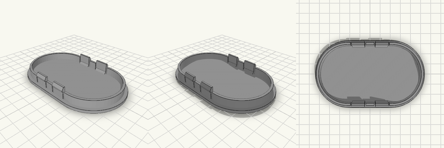
100x59 Oval Body Hole Cover with Snap Clips
Einsteckbare Abdeckung für eine ovale Öffnung von 100 × 59 mm in etwa 1 mm dickem Blech. Die Frontplatte ist vollständig geschlossen und liegt mit einem 3 mm breiten Auflageflansch rundum auf dem Blech auf; außen misst die Abdeckung 106 × 65 mm bei 2,5 mm Plattendicke. Auf der Rückseite zentriert ein Rahmen mit 2 mm Wandstärke und einer Innenöffnung von 96 × 55 mm als ovales Langloch mit Endradius 27,5 mm. Der Rahmen reicht 7 mm über den Flansch hinaus. Die vier flexiblen Clips – je zwei an den langen Kanten – haben 0,8 mm hohe Haken und angeschrägte Einführflächen; die Rastkante sitzt 7 mm über der Flanschfläche. Mit den verlängerten Federschlitzen baut die Abdeckung insgesamt 13 mm hoch. Bei 1 mm Blech bleibt zwischen Blech und Rastkante in Einsteckrichtung Luft; der Clip rastet erst nach 7 mm Einstecktiefe ein. Werkzeuglose Montage und Demontage Einteiliger Körper, keine Schrauben und kein Kleber Flansch nach unten drucken, in PETG oder ASA Clipsitz beim ersten Druck prüfen, da die Federwirkung des Materials schwankt
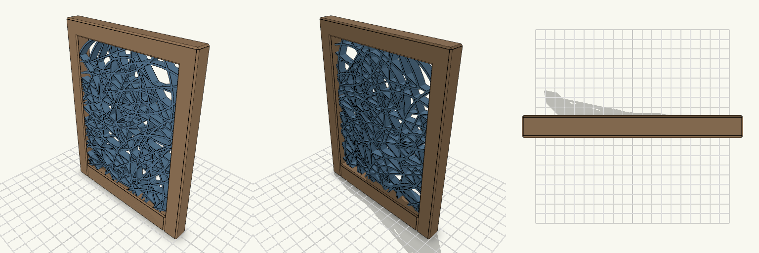
Veranda End Bay with Leaf Outline Infill
A rectangular end frame for a veranda run, built from two uprights, a top beam and a lower rail, with a decorative leaf panel set into the opening. The infill is a collage of large overlapping leaves drawn as open outlines. Each leaf has a centre rib and four angled side veins, so the panel reads as fine, see-through line work rather than a solid fill. Leaves sit at random angles and positions and are clipped flush at the frame, where edge leaves run into the posts, top beam and bottom rail. A leaf sits one third of the way in from the left post, just under halfway up the panel. Frame and infill print as one piece. What it's for Closes the end of a veranda run with a decorative open screen instead of a solid infill. The overlapping leaf outlines fill the panel with line work while leaving gaps open, so sightlines and airflow stay partly clear. The scattered leaf layout gives an organic, uneven look rather than a repeating geometric pattern. The layout is fixed, so the pattern is the same from print to print. Dimensions Overall frame: 120 × 150 mm, 12 mm deep. Infill opening: about 96 × 123 mm, 6.5 mm deep; the leaf collage fills it edge to edge. Leaves: roughly 50–105 mm long and 26–46 mm wide, with a 1.2 mm outline, a 1 mm centre rib and four side veins at 0.8 mm. Frame and infill print as one piece; no assembly required. Print notes Lay the frame flat on the plate and print it as a single piece. The leaf outlines, ribs and veins are thin line work; slow the outer walls if the printer tends to string across the gaps. Because the leaves are placed at random, a leaf near the edge may be held only by its neighbours rather than by the frame. Check the perimeter first when cleaning up the print. Remix ideas Change the frame proportions to suit a different veranda or porch opening. Reuse the leaf collage alone as a decorative screen or window insert. Simplify the leaf outlines for a bolder, less detailed screen. Swap the leaf shape for a different botanical outline while keeping the scattered layout.
Need a part that doesn't exist yet?
Start building →